
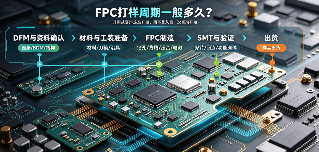
When customers ask about FPC prototyping lead time, manufacturers usually count days starting from data finalization—not from the initial inquiry. DFM review, material sourcing, tooling, manufacturing, inspection, SMT, and reliability validation all impact timing. This article breaks down the timeline by phase and explains how to accelerate it without compromising quality.
Lead time is counted from 'data finalization'—not from the first customer inquiry.
After a customer submits a drawing, they often assume prototyping has begun; however, the manufacturer typically waits until Gerber files, stack-up, material specs, BOM, quantity, and acceptance criteria are confirmed before releasing material. This misalignment in starting points frequently causes delivery misunderstandings. Quotation documents should clearly specify the data finalization date, bare-board completion date, and final sample shipment date.
Phase One: DFM Review and Data Confirmation
Engineering teams verify line width/spacing, hole size, bend zones, stiffeners, connectors, panelization, and test points. Complex projects may require customer drawing revisions. Though no physical production occurs here, this step prevents downstream scrap and rework. Inconsistent versions among drawings, BOMs, and 3D mechanical structures are common causes of schedule delays.
Phase Two: Material and Tooling Preparation
Standard polyimide (PI), copper foil, and coverlay with existing inventory can be released quickly; however, specified brands, non-standard copper thicknesses, high-Tg materials, custom stiffeners, or specialized connectors may require procurement. Die-cut tooling, electrical test fixtures, stencils, and assembly jigs also take time to prepare. Quotations should distinguish between in-stock materials and custom-sourced items.
Phase Three: FPC Manufacturing
Key steps include material cutting, drilling, circuit imaging, etching, AOI inspection, coverlay lamination, hot-press lamination, surface finishing, routing, and electrical testing. Multi-layer designs, fine-line circuits, large panel sizes, or special surface finishes add process steps and waiting time. First-article approval is required between each operation—total lead time cannot be estimated simply by summing equipment processing times.
Phase Four: SMT and Validation
For FPCA delivery, additional steps include stencil preparation, component staging, pick-and-place, reflow soldering, AOI, solder joint inspection, and functional testing. Bend testing, thermal cycling, impedance measurement, or other reliability validations must be scheduled separately—and must not be conflated with standard bare-board delivery timelines.
How to Reasonably Shorten Prototyping Lead Time
- Submit Gerber files, BOM, stack-up, mechanical structure, and acceptance criteria in one complete package during quotation.
- Internally freeze document versions early, designate a single data release window, and maintain a formal change log.
- Prioritize proven, in-stock materials and mature processes—avoid pushing extreme parameters unless absolutely necessary.
- Prepare bare-board fabrication, SMT, and reliability validation in parallel—but never skip DFM review.
- Confirm post-receipt test plans in advance to avoid idle time after sample arrival.
Hongyi Precision provides node-based prototyping schedules tailored to project complexity. True rapid prototyping does not mean compressing essential steps—it means minimizing data iterations, waiting time, and repeated revisions so the first sample closely meets mass-production requirements.