
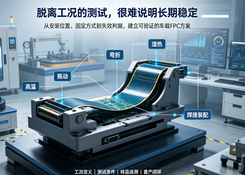
Automotive flexible printed circuit (FPC) reliability cannot be assessed by continuity and visual inspection alone—it requires validation protocols tailored to temperature, vibration, humidity-heat, bending, soldering, and assembly conditions. This article outlines key steps from operational input to result evaluation.
Once installed in a vehicle or subsystem, automotive flexible printed circuits (FPCs) may simultaneously experience temperature extremes, sustained vibration, dynamic bending, humidity-heat, thermal shock from soldering, and mechanical stress from assembly. Reliability validation that ignores mounting location and real-world operating conditions—and relies instead on generic test sets—cannot reliably predict long-term performance.
Early in the project, automotive FPC manufacturers and customers should jointly define usage boundaries before finalizing test items, sample sizes, duration, and failure criteria. An effective validation plan is not about maximizing test count; each test must directly address a specific field risk.
1. Risk Definition Starts at the Mounting Location
Temperature, vibration, spatial constraints, and motion profiles differ significantly across locations such as gear shifters, steering wheels, seats, door panels, instrument clusters, and center consoles. Locations near heat sources demand focused assessment of continuous high-temperature stability and thermal cycling; areas with mechanical actuation require additional evaluation of bending, torsion, and connector loading.
Customers should provide mounting location, fixation method, motion trajectory, proximity to heat sources, connector design, operating current, and target system lifetime. Without these inputs, material selection and test parameters remain based on empirical estimation rather than engineering rationale.
2. Temperature Validation Must Differentiate Continuous High-Temperature Exposure from Thermal Cycling
Continuous high-temperature testing evaluates long-term stability of substrate materials, adhesive layers, coverlays, surface finishes, and solder joints. Thermal cycling more readily reveals warpage, delamination, and contact degradation caused by mismatched coefficients of thermal expansion among dissimilar materials.
Test plans must explicitly specify temperature ranges, ramp rates, dwell times, cycle counts, power state during testing, and electrical/visual inspections pre- and post-test. Stating only 'withstands X°C' is insufficient for executable acceptance criteria.
3. Vibration and Bending Tests Must Replicate Actual Fixation Methods
The same FPC exhibits different stress paths under vibration depending on fixture point configuration. Connector support, housing clamping, exit direction, and harness pull forces all influence outcomes. Dynamic bending tests must define bend radius, direction, stroke, frequency, cycle count, and in-situ monitoring methodology.
When developing test fixtures, automotive FPC manufacturers should replicate critical constraints present in the final assembly. Post-test evaluation must go beyond open-circuit detection to include resistance change, intermittent opens, pad integrity, stiffener condition, coverlay adhesion, and connector retention status.
4. Humidity-Heat, Salt Spray, and Soldering/Assembly Effects Must Not Be Overlooked
Locations near external environments or sealing interfaces may require evaluation for humidity-heat, condensation, salt spray, and corrosion. Exposed bare copper, pads, connector terminations, and surface finishes should be tested according to actual exposure conditions.
If the FPC undergoes SMT, reflow soldering, connector assembly, or manual insertion/removal, thermal energy from soldering, insertion force, retention force, and mechanical pulling during assembly must also be included in validation. Electrical continuity of traces alone does not guarantee pad or connector interface robustness under full-system operation.
5. Reports Must Clearly Document the Following
Drawing revision, material lot number, and sample quantity.
Test equipment, fixtures, mounting method, and power state.
Specific test conditions for temperature, vibration, bending, humidity-heat, etc.
Electrical, dimensional, visual, and assembly results pre- and post-test.
Failure criteria, anomaly photographs, root cause analysis, and corrective actions.
Only with fully defined reporting boundaries can procurement, R&D, and quality teams objectively compare validation results across different automotive FPC suppliers.
Automotive FPC manufacturers must also ensure production consistency.
Validation success for one batch does not guarantee inherent consistency in subsequent lots. During pilot production and mass production, ongoing tracking of material lots, critical process parameters, AOI results, electrical test data, defect distribution, and closed-loop anomaly resolution is essential.
Hongyi Precision manages processes per IATF 16949, ISO 9001, and ISO 14001 standards, providing design evaluation, prototyping, reliability validation, and volume delivery support for FPC and FPCA solutions targeting automotive electronics. Specific validation items are developed collaboratively based on customer system specifications, mounting conditions, and mutually approved test plans.
Conclusion
Automotive FPC reliability is not defined by isolated temperature or bending values—it emerges from the interaction of materials, structure, manufacturing process, assembly method, and environmental exposure. When selecting an automotive FPC supplier, prioritize those capable of translating real-world operating conditions into precise test parameters—and closing the loop from test results back to design and production.
Note:This article supports early-stage technical discussions for automotive FPC projects. Final metrics and acceptance criteria shall follow the customer’s system-level specifications, actual mounting conditions, and mutually confirmed test plans.