
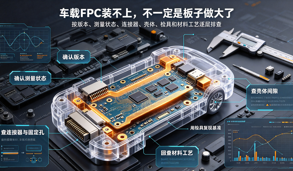
When vehicle-mounted FPCs encounter installation difficulties, root causes may lie in measurement reference, flex state, connector end, mounting holes, or inspection fixtures—not just overall length and width. This article outlines the field troubleshooting sequence for accurate root-cause identification.
When a vehicle-mounted FPC fails to install, the most common first question on the shop floor is: 'Is the board oversized?' Yet this is only one possible cause. An FPC’s shape changes depending on whether it’s in free state, fixture state, or assembled state; connector ends, mounting holes, stiffeners, and housing constraints can impact installation more directly than overall length and width.
Below is a step-by-step field troubleshooting sequence to help FPC manufacturers and customer engineering teams break down the vague symptom 'won’t install' into measurable, verifiable issues.
Step 1: Confirm product revision consistency.
Verify part number, drawing revision, engineering change notices, BOM, connectors, stiffeners, and packaging labels. When new and old revisions are mixed, dimensional differences likely stem from design changes—not manufacturing variation.
Simultaneously confirm that the customer’s housing, connectors, and fasteners are also approved revisions. Without synchronized revisions between the FPC and its assembly, measuring the bare FPC alone yields inconclusive results.
Step 2: Return the FPC to its specified measurement condition.
In free state, an FPC may naturally curl, warp, or rebound. Do not arbitrarily stretch or flatten it before measuring all dimensions and then compare those results directly against assembly references. Drawings must clearly specify which dimensions are measured in free state and which require verification using fixtures or in assembled state.
If morphology varies significantly across the same lot, record environmental conditions, storage history, material batch, and lamination status to rule out dimensional shift caused by material expansion/contraction or forming rebound.
Step 3: Prioritize inspection of the connector end and mounting holes.
Connector thickness, stiffener flatness, contact point location, insertion depth, and locking mechanism often cause installation failure more readily than overall length. Mounting hole misalignment, diameter, neck width, and branch length may force unintended stretching—leading to stress concentration after assembly.
On-site, perform localized verification first using actual connectors and positioning features. Then determine whether the issue lies with end dimensions, hole placement, or overall contour—more efficient than reworking the entire panel upfront.
Step 4: Inspect housing edges and motion clearance.
After installation into the housing, clips, screws, burrs, harnesses, and adjacent components may alter the FPC’s routing path. Even if the bare board’s outline meets spec, it may be pinched, abraded, or restricted from bending during assembly.
For electronic shifters, sensors, and body control applications, verify free length, bend radius, connector exit direction, and mounting points under extreme mechanical postures. Assembly validation isn’t just about 'fitting in'—it must ensure no sustained pulling occurs post-installation.
Step 5: Use fixtures to replicate true functional references.
For products requiring multi-point location, curved-surface conformity, or connector mating, rely on validated fixtures or actual housings. Fixture revision, locating features, orientation, wear condition, and calibration cycle must all be controlled.
If conclusions differ between fixture and customer housing, first compare their constraint conditions and reference systems—not immediately assume one is incorrect.
Step 6: Trace back to material and process trends.
Dimensional anomalies may originate from material expansion/contraction, lamination, exposure alignment, etching, final forming, stiffener bonding, or ambient conditions. Correlate field samples with first-article, in-process, finished-good, and assembly data to identify whether anomalies cluster within a specific lot, machine, or board region.
If design, material, equipment, process, or fixture parameters change, re-evaluate dimensional and assembly boundaries. Unapproved on-site adjustments may resolve one lot—but propagate issues to subsequent lots.
Hongyi Precision supports automotive electronics, electronic shifters, sensors, and intelligent cockpit applications with FPC and FPCA dimensional and structural review, fixture compatibility assessment, engineering prototyping, assembly confirmation, reliability validation, and volume production support. Specific tolerances, measurement methods, and release criteria follow customer drawings and quality agreements.
Conclusion:When a vehicle-mounted FPC won’t install, first confirm revision alignment, then verify measurement condition and reference, followed by connector end, mounting holes, housing constraints, and fixture performance—finally tracing back to material and process data. Following this sequence typically identifies the true root cause faster than modifying outline geometry outright.