
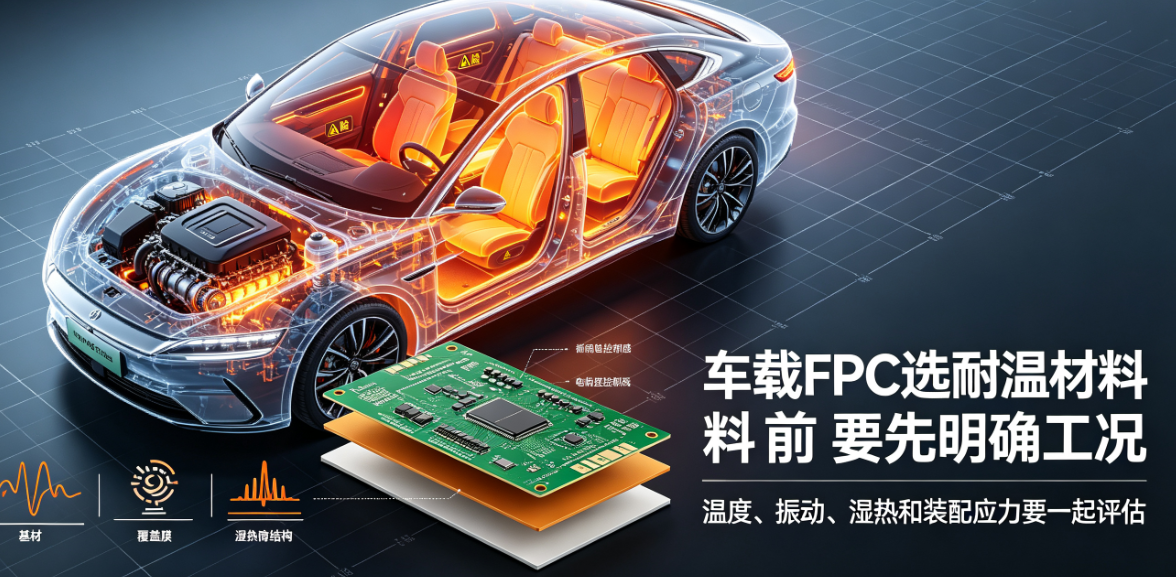
Temperature, vibration, damp-heat, and assembly stress vary significantly across vehicle locations. FPCs installed near heat sources, in engine compartments, or near motor control units face different environmental conditions than those in cabins, door panels, or seat interiors. Therefore, material selection cannot rely on a single 'temperature rating'—an actual operating condition window must first be established.
Define actual operating conditions before selecting high-temperature-resistant materials for automotive FPCs.
Temperature, vibration, damp-heat, and assembly stress vary significantly across vehicle locations. FPCs installed near heat sources, in engine compartments, or near motor control units face different environmental conditions than those in cabins, door panels, or seat interiors. Therefore, material selection cannot rely on a single 'temperature rating'—an actual operating condition window must first be established.
Environmental data to collect:
- Normal operating temperature and short-term peak temperature;
- Temperature cycling range and duration;
- Exposure to damp-heat, condensation, salt spray, or chemical media;
- Vibration, mechanical shock, and assembly stress induced by vehicle motion;
- Static bending, dynamic bending, and minimum assembly bend radius;
- Signal integrity, current-carrying capacity, connector interface, and housing clearance requirements.
Installation zones cannot share identical evaluation criteria.
Installation Environment Primary Risks Key Review Points Cabin or center console area Temperature cycling, assembly bending, connector contact reliability Housing space constraints, end stiffeners, long-term contact stability Door, seat, and other moving areas Repeated motion, vibration, harness pulling Bending trajectory, fixation points, abrasion protection Near motor or heat source Elevated temperature, vibration, EMI Material system, return path design, shielding, thermal dissipation Humid or condensation-prone areas Damp-heat, ionic contamination, corrosion risk Cover protection, cleanliness, connector sealing, and housing structureActual vehicle boundary conditions must be defined by the vehicle OEM or component program. The above table serves only for risk identification—not as a substitute for customer-defined environmental specifications. Especially distinguish between continuous operating temperature, short-term peak temperature, storage temperature, and test temperature—they carry distinct meanings.
Materials and structure must be evaluated holistically.
The base film, copper foil, coverlay, adhesive layer, stiffener, and surface finish collectively determine dimensional stability and interconnect reliability under thermal cycling. Bending zones, soldered areas, and connector interfaces require separate assessment to prevent delamination, warpage, contact instability, or resistance drift after high-temperature exposure.
Copper foil type and trace orientation affect bending fatigue life; adhesive and coverlay properties influence high-temperature performance, damp-heat resistance, and peel strength; stiffener material and adhesive system impact rigidity-to-flex transition and dimensional stability; surface finish must match soldering process, connector mating, and storage conditions. A standalone 'high-temperature PI' specification does not guarantee that the finished FPC meets project requirements.
For current-carrying traces, calculate the combined effect of self-heating and ambient temperature. Localized narrow traces, connector terminals, and solder joints may become hotspots—validate via design calculation and sample thermography, rather than relying solely on material datasheet temperature ratings.
Recommended validation approach:
Develop thermal cycling, damp-heat, vibration, mechanical bending, continuity, and visual inspection protocols aligned with vehicle or component requirements. Prior to testing, define sample quantity, power-on status, failure criteria, pre-/post-test electrical performance comparison, and batch traceability method. Test conditions must reflect actual mounting configurations.
Recommend establishing a validation matrix:
A validation matrix can be organized by 'Risk–Test–Monitoring–Judgment'. For example: thermal cycling relates to delamination, warpage, and contact variation; vibration relates to intermittent opens, connector loosening, and stiffener edge damage; damp-heat relates to insulation degradation, corrosion, and interface changes. Each test must specify sample status, fixture setup, power-on conditions, and pre-/post-test inspection items.
When FPCs simultaneously endure temperature, vibration, and bending, passing individual tests does not fully represent combined-condition performance. The project team may decide—based on risk—whether sequential or combined testing is required, and must document test sequence, as order may affect outcomes.
Situations requiring revalidation after change:
Revalidation impact assessment is required when changing material grade, copper thickness, adhesive system, stiffener, surface finish, critical trace layout, connector, or manufacturing process. Not all changes necessitate full retesting, but affected performance attributes and required supplementary validation must be explicitly identified—and approval records retained.
Common questions:
Does a higher temperature rating always mean better suitability?Not necessarily—bending capability, adhesive performance, connector compatibility, and assembly conditions must also be satisfied concurrently.
Can consumer-grade FPCs be directly used in automotive applications?No direct inference is valid. Materials, structure, process, and validation evidence must be reassessed against automotive-specific operating conditions.
Does passing high-temperature storage testing confirm adequate temperature resistance?It does not address all concerns. Operational state, thermal cycling, damp-heat, vibration, and assembly stress may induce distinct failure modes.
Are AEC-Q qualifications applicable to automotive FPCs?AEC-Q standards target discrete electronic components by category and are not directly applicable as certification for finished FPCs. FPCs must be validated per vehicle OEM, component, IPC, and customer project specifications.
This article was compiled by Hongyi Precision based on recurring issues observed during technical reviews of automotive flexible circuit board projects. Final selection of automotive FPCs must be based on project-specific environmental specifications and sample validation results. Process management should also align with customer quality systems and IATF 16949 requirements.