
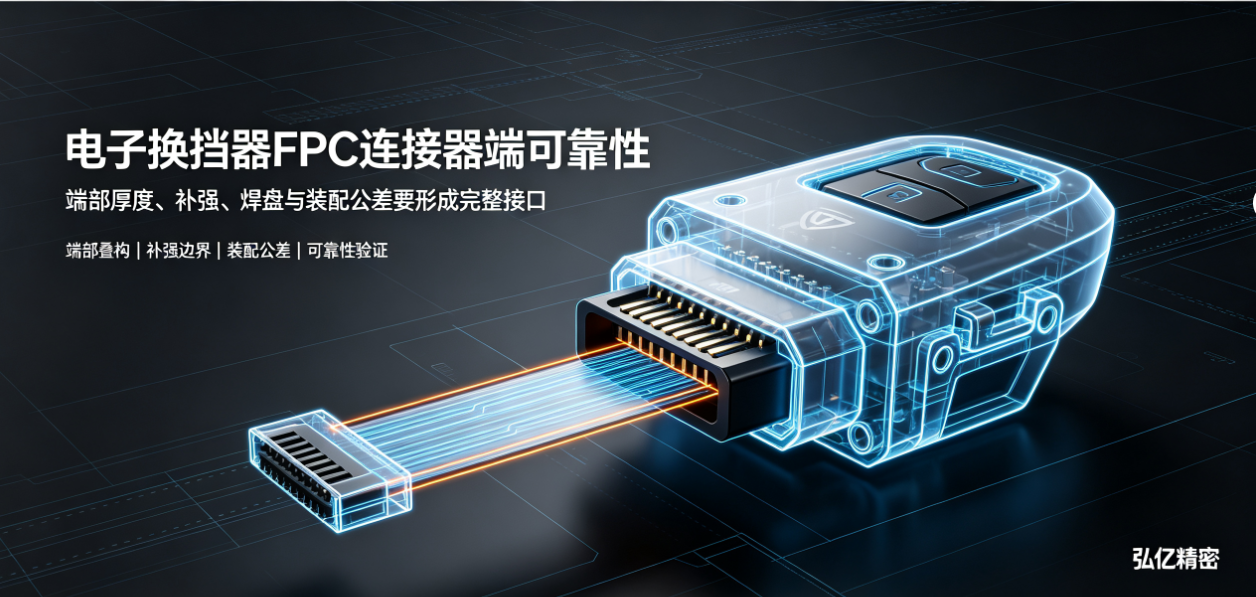
The connector end of an electronic shifter FPC simultaneously handles positioning, mating/unmating, electrical connection, and mechanical loading during assembly. Poor design can lead to abnormal insertion force, unstable contact, or pad damage. This article summarizes key review points for the connector end.
When unstable contact occurs in electronic shifter FPCs, many engineers first suspect connector quality or soldering process. In reality, mismatched thickness, stiffener design, pad layout, mating direction, and assembly tolerances at the FPC connector end can also cause abnormal insertion force, insufficient retention force, terminal misalignment, or pad damage.
The connector end is not merely a locally thickened region—it is the interface where the FPC interacts with the connector, housing, and mechanical structure. FPC manufacturers for electronic shifters should verify the following aspects sequentially during design review.
1. First, confirm actual requirements of the connector and terminals
Specify the connector model, terminal pitch, mating direction, latching mechanism, mating cycles, retention force, and allowable end thickness. Different connectors impose significantly varying requirements on total FPC thickness, stiffener material, and dimensional tolerances.
Labeling only 'add stiffener' on a 2D drawing—without providing connector specifications or assembly datums—leaves the manufacturer unable to assess whether stiffener thickness will prevent full insertion or result in insufficient contact pressure.
2. End thickness must account for all stack-up layers
Final connector-end thickness is not determined by base film or copper alone, but by the combined contribution of PI, copper, adhesive, coverlay, stiffener, and surface finish. Local windowing and layer transitions may introduce step changes in end thickness.
During design, define measurement locations, allowable tolerances, and measurement methods. For multi-layer stiffeners or localized bonding structures, confirm potential warpage, burrs, or insertion interference during DFM review.
3. Stiffener boundaries must avoid motion zones and stress concentrations
While stiffeners are typically applied to ensure flatness and mating rigidity at the connector end, the stiffener edge represents an abrupt rigidity transition. If placed near the dynamic bending origin of the shifter mechanism, operational stress may concentrate at the stiffener edge.
FPC manufacturers for electronic shifters should determine stiffener length, thickness, and transition distance based on 3D assembly models and motion trajectories. Stiffeners should support positioning and mating—not rigidify the entire FPC segment.
4. Pad layout must accommodate mating and assembly forces
Avoid placing vias or sharp corners near pads, gold fingers, or contact points where bending-induced strain may occur. Provide adequate transition zones between pad roots, coverlay openings, and stiffener edges to minimize localized stress.
If components, wires, or shielding structures must be soldered at the connector end, thermal input from soldering and mechanical pull forces during handling must also be factored into design. A pad passing static electrical testing does not guarantee robustness under assembly stress or long-term vibration.
5. Assembly tolerances directly impact contact reliability
Dimensional chains exist among FPC outline, connector location, housing clips, mounting holes, and cable exit orientation. Ambiguous definition of any datum may cause lateral FPC offset after assembly, resulting in uneven terminal loading.
Perform 3D assembly tolerance stack-up analysis—including worst-case scenarios—and verify whether the FPC risks scraping against housing edges, compression by clips, or tension from harness routing. For high-cycle mating or actuated mechanisms, also validate assembly sequence and rework feasibility.
6. How to validate the connector end
Validation items include end dimensions, profile, insertion force, retention force, contact resistance, mating durability, vibration resistance, temperature cycling, and dynamic actuation post-assembly. Testing must use actual connectors, housings, and mounting structures—not bare FPCs alone.
Compare contact resistance, continuity, end wear, pad integrity, stiffener condition, and coverlay status before and after testing. When contact anomalies occur, correlate failure location with root causes—thickness mismatch, positional offset, terminal loading, material behavior, or assembly issues.
Documentation to provide FPC manufacturers for electronic shifters prior to prototyping:
Connector model, terminal diagram, and mating direction;
Required connector-end thickness, stiffener specifications, and surface finish;
3D assembly model including mounting holes, clips, and motion trajectory;
Mating cycles, retention force, contact resistance, and operating temperature conditions;
Soldering, SMT, harness integration, and full-system assembly methods;
Dimensional, electrical, reliability, and cosmetic acceptance criteria.
Hongyi Precision serves automotive electronics applications—including electronic shifters, column-mounted shifters, and gear position sensing—with FPC and FPCA connector-end design evaluation, DFM support, engineering prototyping, assembly validation, and volume production. Specific thickness, stiffener, and pad solutions are finalized jointly with customers based on their connector, mechanical structure, and operational conditions.
Summary:Reliability of the electronic shifter FPC connector end depends on seamless integration of end thickness, stiffener, pad layout, connector, housing, and assembly tolerances into a unified interface. Adjusting only one parameter rarely resolves all post-assembly issues.