
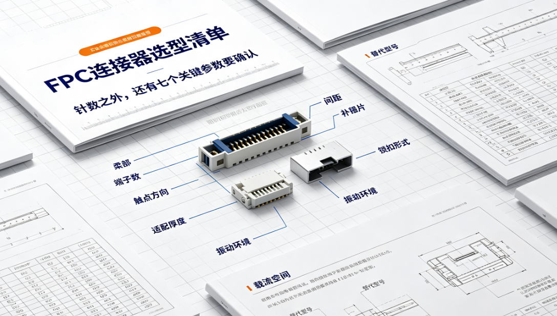
A connector must simultaneously match the FPC’s contact configuration, thickness, stiffener, trace count, signal type, and available assembly space. Even if the FPC itself is electrically sound, mismatched models may cause insertion difficulty, unstable contact, or inconsistent mass-production assembly.
FPC connector selection must not focus solely on pin count.
A connector must simultaneously match the FPC’s contact configuration, thickness, stiffener, trace count, signal type, and available assembly space. Even if the FPC itself is electrically sound, mismatched models may cause insertion difficulty, unstable contact, or inconsistent mass-production assembly.
The following parameters should be confirmed during selection:
- Terminal count, contact orientation, and connector pitch;
- Finished FPC thickness, stiffener thickness, and insertion length;
- Top-mount, bottom-mount, or dual-mount structure, plus latch type;
- Rated current, voltage, and high-speed signal impedance requirements;
- Mating cycle count, retention force, and vibration resistance requirements;
- Operating temperature, humid-heat environment, and internal housing space;
- Connector supply stability, alternate part numbers, and assembly process compatibility.
The 'compatible FPC thickness' listed in a connector datasheet typically refers to the finished thickness at the contact area. Engineers must calculate total thickness—including copper foil, substrate, coverlay, surface finish, and stiffener. An undersized finished FPC may lack sufficient retention force; an oversized one may resist insertion or damage terminals.
FPC end design must align with the connector.
A stiffener is typically required in the connector area to ensure insertion rigidity and dimensional stability. The length, surface finish, chamfer, exposed copper area, and solder mask design of gold fingers or contact pads must all conform to the connector’s datasheet. If the FPC requires bending near the connector, the bend path must be evaluated alongside latch operation clearance.
End tolerances cannot be determined in isolation. FPC overall width, contact centerline position, stiffener edge location, and insertion datum collectively determine assembly consistency. For connectors with fine pitch, confirm manufacturable tolerances and inspection methods with the FPC supplier—and specify a unified datum on drawings.
Selection workflow—from datasheet to sample:
Step 1: Define electrical and mechanical interfaces; screen candidate models meeting terminal count, pitch, orientation, and environmental requirements; Step 2: Obtain official datasheets and recommended FPC end dimensions; Step 3: Finalize end and stiffener design; Step 4: Fabricate samples and perform assembly; Step 5: Validate under actual harness routing, housing constraints, and dynamic motion conditions.
If a second-source connector is required, key dimensions should be cross-checked early in design. Visual similarity does not guarantee identical terminal contact force, latch geometry, pad layout, or compatible thickness. Alternate validation must cover assembly, electrical, and environmental performance.
Recommended sampling validation:
Conduct repeated mating/unmating cycles, continuity checks, contact resistance measurement, retention force testing, and assembly trials during sampling. For automotive or robotic applications, retest contact stability under thermal cycling, vibration, and real-world assembly stress.
Record connector batch number, FPC batch number, mating cycles, handling method, and failure modes during testing. A single power-on check is insufficient to detect issues such as incomplete latch engagement, thickness variation-induced misalignment, or intermittent opens after vibration. For high-speed interfaces, validate signal integrity across the full channel—including both connector and FPC.
Common Questions:
Can connectors with identical pin counts be interchanged?No—pitch, contact orientation, thickness, latch design, and mounting dimensions must all be verified.
Why is stiffening commonly required in the connector area?Stiffening improves insertion rigidity and dimensional stability, reducing contact issues caused by end deformation.
Are longer gold fingers always better?No—length must match terminal contact position and insertion depth. Excess length wastes space or increases exposed area; insufficient length risks poor contact.
Does successful sample insertion guarantee dimensional compliance?No—it does not confirm proper latch engagement, retention force, contact stability, or batch-to-batch tolerance robustness, which may lead to assembly failures in mass production.
This article was compiled by Hongyi Precision based on common review issues encountered in FPC connector projects. Final model selection must be based on the connector’s official datasheet, FPC fabrication drawings, and system-level assembly validation results.