
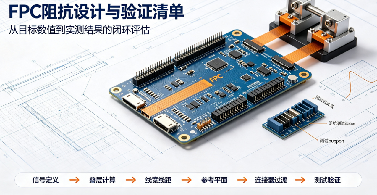
When FPCs are used for high-speed or high-frequency signal interconnects, trace geometry, dielectric thickness, and material dielectric properties affect signal reflection and transmission loss. Impedance control is not achieved by adjusting trace width alone—it requires integrated evaluation of stack-up, traces, coverlay, and interconnect structures.
Why Impedance Matters for FPCs
When FPCs are used for high-speed or high-frequency signal interconnects, trace geometry, dielectric thickness, and material dielectric properties affect signal reflection and transmission loss. Impedance control is not achieved by adjusting trace width alone—it requires integrated evaluation of stack-up, traces, coverlay, and interconnect structures.
Key Factors Affecting FPC Impedance
- Trace Width and Copper Thickness: Wider traces and thicker copper shift impedance trends; manufacturing tolerances must also be factored into calculations.
- Dielectric Thickness: The distance between the trace and its reference plane significantly impacts impedance; coverlay thickness may also contribute to the effective dielectric.
- Material Dielectric Properties: Different substrates, adhesive layers, and coverlays exhibit varying dielectric constants—generic parameters cannot be applied universally.
- Reference Plane and Return Path: Both differential pairs and single-ended traces require clearly defined reference layers, adjacent trace spacing, and continuous return paths.
- Connectors and Transition Zones: Pads, stiffeners, connectors, and transition structures may introduce localized discontinuities.
Design Considerations by Structure Type
Structure Type Primary Focus Areas Commonly Overlooked Issues Single-Ended Trace Trace width, dielectric thickness, reference plane continuity Return path interrupted by slots or vias Differential Pair Individual trace width, line spacing, length matching, and coupling Controlling total impedance only, ignoring asymmetry between pair members Coplanar Structure Trace-to-ground-copper spacing, coverlay thickness vs. copper thickness Local ground copper shape changes causing impedance jumps Connector Transition Pads, window openings, stiffeners, and terminal models Main trace meets spec but strong reflections occur at interfaceImpedance design inputs should specify more than just a target value—they must define whether the requirement is for single-ended or differential impedance, reference layer, tolerance, test location, and inclusion (or exclusion) of connector transitions. For differential signals, intra-pair length matching, inter-pair spacing, and return path continuity must also be verified.
Typical FPC Impedance Design Workflow
First confirm signal type, target impedance, operating frequency, trace length, and interconnect method. Then, engineers perform field-solver simulations or impedance calculations based on the selected material stack-up, outputting required trace width, spacing, and layer specifications. Upon design completion, impedance tolerances and test methods must be documented in drawings or inspection specifications.
A robust design workflow typically includes: defining interface requirements, developing candidate stack-ups, performing calculations with actual supplier-provided material parameters, evaluating manufacturability tolerances, verifying feasible trace widths and spacing, generating test structures, and refining the design based on first-round test results. Calculations should use stable, production-grade material thicknesses and copper thicknesses—not theoretical nominal values.
Does Bending Affect High-Speed Signals?
Bending itself does not necessarily cause impedance failure—but excessively small bend radii may alter interlayer distances, induce copper foil strain, or shift the relative position between signal traces and reference planes. For dynamic flex applications, crack formation and resistance drift after repeated bending cycles must also be assessed. Therefore, high-speed FPCs require functional or signal integrity validation under their actual installed configuration—not flat-state testing alone.
How to Validate During the Sample Stage
Validation can be performed using impedance test boards, test coupons, or time-domain reflectometry (TDR). Test location, sample condition, connection method, and pass/fail criteria must be defined at project kickoff. Testing only a local section of the main board cannot represent full FPC performance—including the entire trace and interconnect structure.
When test results deviate from targets, troubleshooting should follow this sequence: measured material thickness → copper thickness → trace width/spacing → reference plane integrity → test fixture setup. If multiple locations across the same batch show consistent deviation, prioritize stack-up and material verification; if anomalies occur only near connectors or pads, focus on local geometry and test connection quality.
Test reports must document sample lot number, test equipment, calibration status, test structure type, target value, measured value, and pass/fail determination. A simple 'pass' conclusion is insufficient for supporting future design revisions or cross-batch comparisons.
Common Questions
Can Adjusting Trace Width Alone Resolve Impedance Deviations?Not necessarily. Deviations may stem from dielectric thickness variation, copper thickness inconsistency, material batch differences, or reference plane shifts.
Can Rigid PCB Impedance Designs Be Directly Applied to FPCs?No. Coverlay, flexible substrate behavior, and dynamic bending conditions alter structural characteristics—impedance must be recalculated and validated using the actual FPC stack-up.
Does Passing Impedance Testing Guarantee Stable High-Speed Link Performance?Not guaranteed. A complete link includes connectors, pads, transition structures, crosstalk, loss, and termination matching.
Should Coverlay Thickness Be Included in Impedance Calculations?Yes—when the coverlay and adhesive layers reside within the electric field region, they influence the effective dielectric environment.
This article was compiled by Hongyi Precision based on recurring issues observed during high-speed FPC project reviews. Impedance targets and tolerances must align with end-device signal requirements and empirical sample test results; design practices may refer to IPC-2223, and test methods may follow relevant sections of IPC-TM-650 and project-specific specifications.