
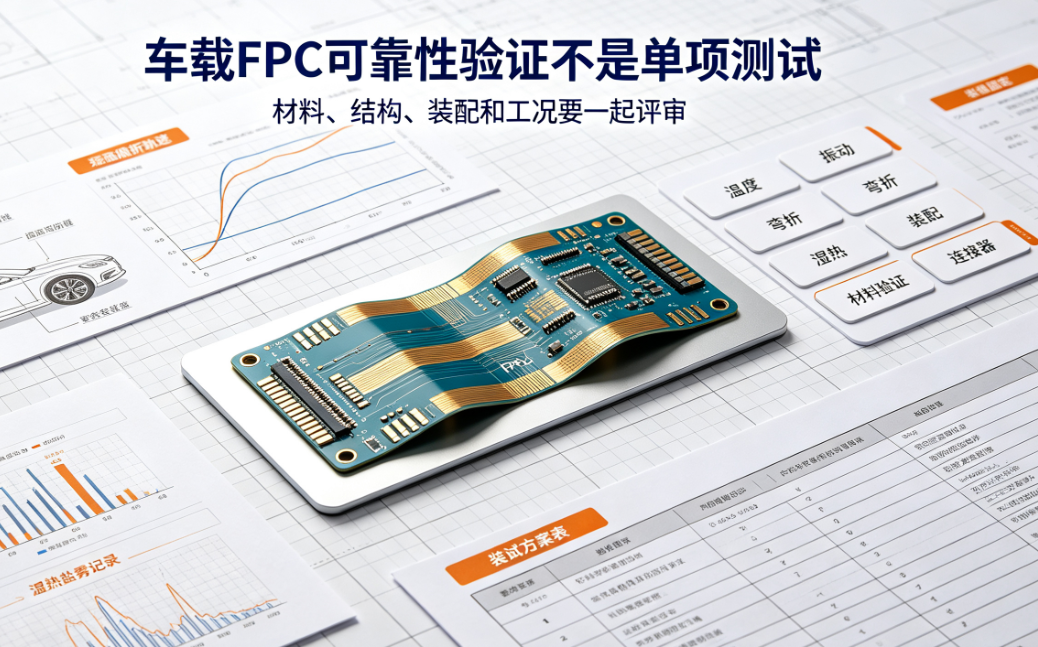
Automotive FPCs cannot be validated on conductivity alone; reliability must be verified under combined conditions including temperature, vibration, flexing, humidity-heat, soldering, and assembly stresses. This article outlines the reliability metrics and documentation FPC manufacturers and customers should jointly confirm early in automotive projects.
In automotive FPC projects, basic electrical continuity is only the minimum requirement. Once integrated into a vehicle or subsystem for long-term operation, factors such as temperature fluctuations, continuous vibration, repeated flexing, humidity-heat exposure, and assembly-induced stress can all compromise trace integrity and interconnect stability.
Therefore, when selecting an FPC manufacturer for automotive applications, it is insufficient to ask only whether they can produce the part — customers must proactively confirm whether the supplier can develop a reliability validation plan tailored to the specific mounting location and operational environment.
1. First, determine where the FPC will be mounted.
Risk profiles vary significantly by mounting location. Temperature, vibration, spatial constraints, and motion characteristics differ across gear shifters, steering wheels, seats, doors, instrument clusters, and center consoles — making a single test profile inappropriate for all locations.
At project kickoff, the customer should provide the FPC manufacturer with details including mounting location, static vs. dynamic flexing, cycle count, harness fixation method, connector architecture, and proximity to heat sources. Without this information, material selection and stack-up design remain reliant on empirical estimation.
2. Temperature metrics must address both sustained and cyclic conditions.
Automotive FPCs typically require evaluation under high-temperature, low-temperature, and thermal cycling conditions. Sustained high temperature primarily assesses stability of base materials, adhesive layers, coverlays, and surface finishes; thermal cycling more readily reveals delamination, warpage, or contact resistance shifts caused by mismatched coefficients of thermal expansion (CTE) among layered materials.
Test specifications should not list only a maximum temperature — they must also define soak duration, cycle count, power state during testing, and electrical performance criteria before and after testing.
3. Vibration and flexing tests must reflect actual assembly conditions.
Vibration test results lose relevance if conducted without replicating real-world mounting methods. Clamp position within the housing, connector support, bend radius, and harness tension all influence load paths and stress distribution.
For dynamic flexing, parameters such as bending direction, minimum radius, reciprocating frequency, cycle count, and real-time continuity monitoring must be explicitly defined. Repeated flat-plane folding does not replicate in-vehicle motion behavior.
4. Humidity-heat and salt spray requirements depend on environmental exposure.
Locations near the vehicle exterior, underbody, or areas prone to moisture ingress may require evaluation for humidity-heat, condensation, salt spray, and corrosion risks. Prior to testing, the condition of pads, connector terminations, exposed copper areas, and sealing structures must be confirmed.
For surface-finished FPCs, the finish type alone is insufficient — performance must be assessed via contact resistance changes after soldering, mating/unmating cycles, and long-term environmental exposure.
5. Soldering and assembly processes are also reliability-critical.
Even if FPC traces pass standalone tests, excessive heat, insertion force, or mechanical pull during assembly can cause pad lifting, cracking, or intermittent opens at pads, stiffeners, or connector interfaces.
Reliability validation should incorporate actual connectors, housings, harnesses, and fixation methods. For SMT or soldered components, pad layout, reflow profile, post-solder cleaning, and visual inspection requirements must also be confirmed.
6. A complete test plan must specify at minimum the following:
Project-required conditions | Key observations Temperature cycling | High/low temperature limits, soak time, cycle count, powered state | Visual defects, delamination, resistance shift, continuity change Vibration | Direction, frequency, acceleration, mounting method | Intermittent opens, connector loosening, trace cracking Dynamic flexing | Bend radius, direction, frequency, cycle count | Resistance variation, copper fatigue, insulation integrity Humidity-heat / Salt spray | Temperature/humidity, duration, salt solution concentration, sample condition | Corrosion, oxidation, insulation degradation, contact stability Assembly validation | Connector, housing, harness, operator actions | Insertion force, retention force, pad/stiffener integrity7. What evidence should procurement request from FPC manufacturers?
Procurement teams are advised to request the manufacturer’s project-specific test plan, sample size, pass/fail criteria, equipment calibration records, raw test data, and nonconformance handling procedures. Generic certifications (e.g., ISO 9001, IATF 16949) serve as baseline references but cannot substitute for application-specific validation.
If a manufacturer proactively identifies flexing, thermal, connector, or material risks during early sampling — and translates those risks into executable test items — it generally reflects stronger engineering review capability.
Conclusion
Automotive FPC reliability is not defined by a single temperature or bend radius value, but rather emerges from the interaction of materials, structure, manufacturing process, assembly method, and service environment.
Hongyi Precision reviews stack-up design, stiffener placement, flex zones, and test requirements based on mounting location and operational conditions for each automotive FPC project — then proceeds to sample and volume validation. Specific metrics shall align with the customer’s project specifications, system-level operating conditions, and mutually agreed test plans.