
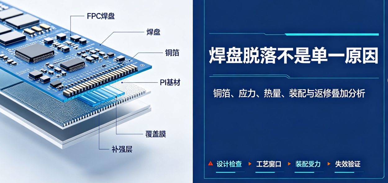
FPC pad detachment may stem from copper foil adhesion, pad dimensions, stiffener design, soldering heat input, flux residue, and assembly-induced pulling forces. Simply replacing materials—without evaluating bending behavior and assembly mechanical stress—often fails to resolve the root cause.
FPC pad detachment is typically the result of multiple overlapping factors.
FPC pad detachment may stem from copper foil adhesion, pad dimensions, stiffener design, soldering heat input, flux residue, and assembly-induced pulling forces. Simply replacing materials—without evaluating bending behavior and assembly mechanical stress—often fails to resolve the root cause.
What should be reviewed during design?
- Whether pads are located within dynamic bend zones or bend transition zones;
- Whether sufficient base material support and stiffening exist around pads;
- Whether sharp corners, abrupt trace narrowing, or stress concentration occur where traces exit pads;
- Whether pad dimensions, solder mask openings, and solder coverage match component requirements;
- Whether pads will experience pulling, peeling, or housing compression after assembly.
Do not immediately clean, re-solder, or cut failed samples. First, photograph the original condition and annotate product batch number, soldering station, assembly orientation, and time of occurrence. When necessary, use microscopy, cross-sectioning, or peel testing to distinguish copper foil fracture, interfacial separation, and solder joint failure.
Common causes during process and assembly stages
Excessive soldering temperature or duration, repeated rework, pad contamination, improper use of peel tools, and suboptimal harness fixation can all impose additional stress on pads. For connectors or large components, verify that solder joints are not the sole mechanical attachment point.
Thermal input differs significantly among reflow soldering, thermocompression bonding, hand soldering, and connector-specific welding—so a generic 'soldering temperature' guideline is inadequate. Establish a process window based on component specifications, solder alloy, equipment capability, and FPC material properties; record peak temperature, time above liquidus, and rework count. Pre-soldering storage, baking, and surface cleaning may also affect wetting behavior and interfacial integrity.
After assembly, mechanical loads on the FPC should be borne by housings, fixtures, or stress-relief structures—not directly transferred to pads. If harness tension transmits force directly to pads, failures may occur during shipping, vibration, or service—even if initial functional testing passes.
Improvement approach
Adjust stiffener coverage, pad trace geometry, mounting method, and soldering parameters based on failure location—and validate changes using peel strength, bend cycling, thermal cycling, and assembly simulation tests. Prior to mass production, retain photos of failed samples, batch information, process parameters, and revision records for full traceability.
Recommended troubleshooting sequence
First, confirm whether issues cluster at specific pads, batches, or workstations; second, compare materials, dimensions, and soldering records between good and defective units; third, replicate actual assembly mechanical loading; finally, verify improvement effectiveness using controlled test samples. Simultaneously modifying material, stiffener, and soldering parameters prevents identification of the truly effective corrective action.
Improvement validation requires explicit pass/fail criteria—e.g., visual inspection, continuity, peel strength, or post-bend performance—and retention of pre- and post-revision samples and data. Observing 'no detachment this time' alone is insufficient to justify mass production release.
Frequently asked questions
Is pad detachment always attributable to the FPC manufacturer’s fabrication quality?Not necessarily. Design-induced stress and assembly handling errors can also cause detachment; root cause must be determined via fracture surface analysis and failure location correlation.
Does increasing solder volume improve pad strength?Excess solder may increase thermal exposure and localized stress—it cannot substitute for structural stiffening or an optimized soldering process window.
Will adding stiffener near pads always resolve detachment?Not necessarily. Improper stiffener edge placement may shift stress to adjacent traces; adjustments must consider load direction and bend path geometry.
Can defective units be reworked with simple re-soldering and reused?Assessment must follow project-specific quality requirements. Simple re-soldering is inappropriate when pad delamination, substrate damage, or repeated rework is involved—as it may conceal underlying reliability risks.
This article was compiled by Hongyi Precision based on common failure modes observed in FPC soldering and assembly processes. We recommend performing failure analysis first—then determining whether design, material, or assembly process adjustments are required. Visual and performance evaluation may reference IPC-A-600, IPC-6013, and customer acceptance criteria.