
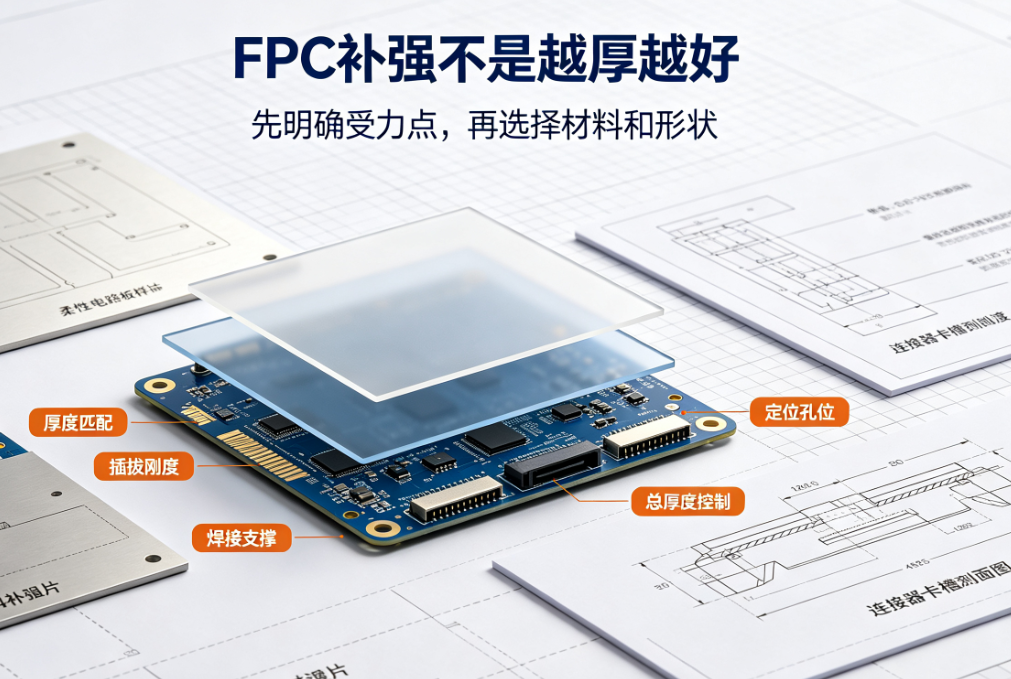
The FPC substrate must retain flexibility, yet areas such as connectors, pads, screw-mount zones, or manual plug-in regions typically require higher rigidity. Stiffeners help control local geometry, support assembly loads, and reduce the risk of repeated bending at pads or interconnection zones. Stiffening is not simply a matter of increasing thickness—the critical factors are location, dimensions, and transition design aligned with the mechanical assembly structure.
Why FPCs Require Stiffeners
The FPC substrate must retain flexibility, yet areas such as connectors, pads, screw-mount zones, or manual plug-in regions typically require higher rigidity. Stiffeners help control local geometry, support assembly loads, and reduce the risk of repeated bending at pads or interconnection zones. Stiffening is not simply a matter of increasing thickness—the critical factors are location, dimensions, and transition design aligned with the mechanical assembly structure.
Common Stiffener Materials
PI StiffenersLightweight and suitable for areas requiring moderate flexibility plus localized rigidity;FR-4 StiffenersHigher rigidity, commonly used in connector or soldering zones;Metal Stiffeners (e.g., Stainless Steel)Offer superior strength and dimensional stability but increase weight, cost, and mechanical constraints. Material selection must consider operating temperature, adhesive system, thickness, and assembly method.
Stiffener Material Key Characteristics Typical Application Locations Critical Review Points PI Thin, lightweight; provides localized rigidity while retaining some flexibility Gold fingers, localized thickness compensation, flexible transition zones Total thickness, adhesive layer, and compatibility with connector housing slots FR-4 High rigidity; compatible with standard PCB assembly processes Connectors, soldering zones, screw-mount or positioning areas Outline tolerances, hole placement, thickness, and warpage Stainless Steel High strength and dimensional stability Space-constrained locations requiring high rigidity Weight, electrical insulation, edge burrs, and cost Other Metals or Composites Support thermal conductivity, EMI shielding, or specialized structural requirements Custom structural zones Electrical isolation, corrosion resistance, coefficient of thermal expansion (CTE), and supply chain stabilityWhen selecting a stiffener, first clarify its functional objective: Is it intended to improve insertion rigidity, support solder pads, control thickness, bear screw load, or restrict bending in a specific zone? Different objectives demand different materials and geometries. Blindly reusing FR-4 from prior projects may result in thickness mismatch or stress transfer into flexible zones.
Key Details to Consider When Designing Stiffeners
- Stiffener edges must not fall directly within dynamic bend zones.
- A controlled stress transition zone must be maintained between the stiffener and adjacent flexible area.
- Connector insertion direction, soldering pressure, and assembly alignment must be factored into dimensional design.
- Stiffener thickness must match connector housing slot depth, enclosure clearance, and bend path geometry.
- For high-temperature or multi-cycle assembly applications, verify adhesive bond strength under actual operating conditions.
Why Stiffener Transition Zones Are Prone to Failure
The stiffener edge represents an abrupt change in rigidity. During assembly or motion, if bending concentrates precisely at this edge, copper traces and coverlay experience cyclic strain—potentially leading to trace cracking, coverlay delamination, or adhesive separation. Mitigation strategies include modifying stiffener contour, adding radii, relocating the bend zone away from the edge, or using enclosure features to redistribute stress.
Design drawings must explicitly specify stiffener material, thickness, adhesive type, outline, hole locations, lamination orientation, and dimensional tolerances. If the stiffener interfaces with a connector, validate the total finished FPC thickness—not just the stiffener thickness alone.
How to Validate Stiffener Design During Prototyping
First inspect sample flatness, placement accuracy, and dimensional compliance; then perform real-world connector mating, soldering, or screw assembly. After assembly, observe whether the stiffener edge contacts the enclosure, whether creasing forms in the flexible zone, and whether pads experience tensile loading. For dynamic applications, conduct bend testing on the fully assembled unit under fixed mounting conditions—and compare electrical continuity and visual appearance pre- and post-test.
Flat-table inspection alone fails to reveal many assembly-induced stresses. Retain assembly photos, fixture dimensions, bend path data, and anomaly locations to support the next DFM iteration.
Common Questions
Does a thicker stiffener always improve FPC reliability?Not necessarily. Excessive thickness increases bending stress and concentrates the rigidity transition between flexible and rigid zones.
Can stiffeners be added later in the design cycle?Local stiffeners can be modified during design revisions, but changes impact outline, thickness, and assembly compatibility—final confirmation should occur before prototyping.
Must FR-4 always be used in connector zones?No. Selection depends on the connector’s required insertion thickness, rigidity, and assembly method—PI or hybrid material solutions may also be appropriate.
Can stiffener edges abut solder pads directly?Edge placement must be evaluated against soldering thermal profile and mechanical load direction. Improper positioning risks stress concentration—compact layout alone is insufficient justification.
This article was compiled by Hongyi Precision based on common challenges encountered in FPC stiffener design. Stiffener material and dimensions must be confirmed through structural review, assembly trials, and, where applicable, bend testing. Relevant design principles align with IPC-2223 and customer-specific assembly specifications.