
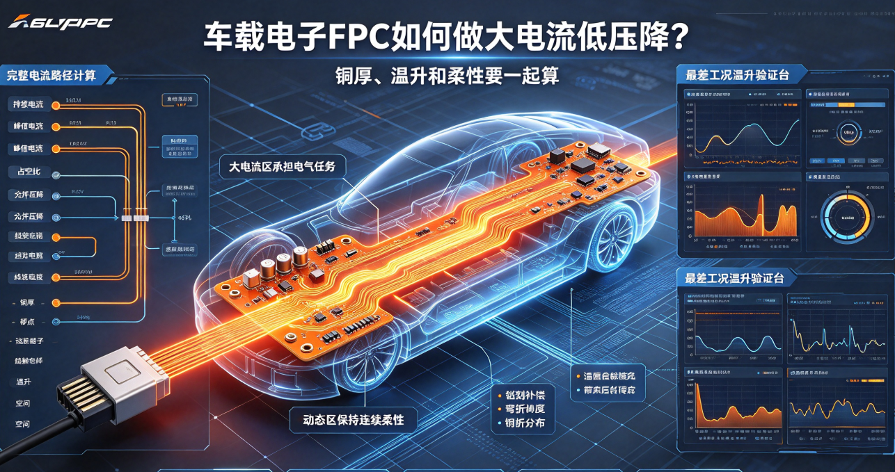
Automotive electronic FPCs used in lighting, seats, door control, and power distribution must simultaneously handle high current, minimize voltage drop, and fit within tight spatial constraints while maintaining flexibility. This article outlines the design methodology—from current path analysis and voltage drop calculation to thermal rise, copper thickness selection, connector integration, and validation.
Automotive electronic FPCs used in ambient lighting, seats, door control, motors, and compact power distribution often require high current capacity, low voltage drop, and bendability simultaneously. Simply widening traces or increasing copper thickness may reduce voltage drop partially but can introduce localized stiffness, lamination fill issues, etching challenges, and thermal management complications. Design must be based on the complete current path.
First, confirm continuous and peak current requirements.
Instantaneous currents during motor startup, full-load lighting, or heating operation may significantly exceed average values. Design must differentiate between continuous, peak, and duty-cycle conditions—and explicitly define allowable voltage drop, temperature rise, and spatial constraints. Selecting trace width based solely on average current may result in dimming, driver reset, or localized overheating during actual operation.
Include connectors and vias in voltage drop calculations.
FPC resistance stems not only from trace length and copper thickness but also from vias, solder joints, connector terminals, and contact resistance. Long-distance power paths should minimize unnecessary transitions and narrow constrictions; connector interfaces must be verified for terminal thickness, locking mechanism, and thermal performance.
What trade-offs accompany increased copper thickness?
Thicker copper foil improves current-carrying capacity but may compromise lamination fill uniformity, etching compensation accuracy, and bending flexibility. When large copper areas coexist with fine-pitch traces, copper distribution balance and panel flatness must also be controlled. In automotive electronic FPCs, high-current zones and dynamic flex zones must be designed separately.
Thermal rise validation must cover worst-case operating conditions.
Under actual housing, connector, and mounting configurations, apply maximum continuous and peak current loads and record temperatures of traces, connectors, solder joints, and adjacent materials. High- and low-temperature environments alter resistivity and heat dissipation—voltage drop and functional performance should be compared across temperature ranges.
Design checklist for high-current FPCs:
Current path, copper thickness, trace width, and minimum neck width;
Vias, solder joints, connectors, and fuses or protection devices;
Transition between dynamic flex zones and large copper areas;
Housing thermal management, insulation, creepage, and clearance;
Voltage drop after full-load operation, peak-current stress, thermal cycling, and vibration testing.
Hongyi Precision evaluates automotive electronic FPCs holistically—considering current-carrying capacity, voltage drop, thermal rise, flexibility, and assembly constraints. A truly manufacturable solution meets electrical performance targets without shifting risk to bending reliability, connector integrity, or thermal robustness.