
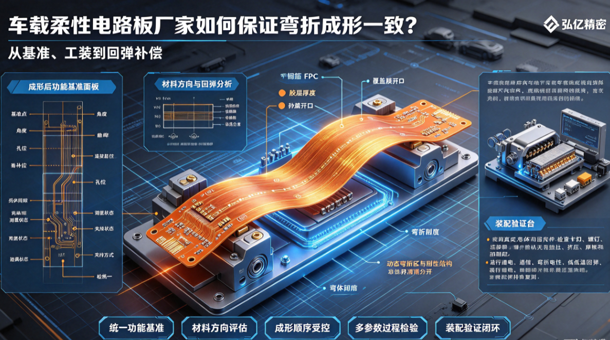
Before installation into vehicle housings, automotive flexible printed circuits (FPCs) often require pre-forming or conforming to curved surfaces. Variations in angle, springback, and positioning across batches can cause assembly interference and stress on circuit traces. This article outlines control methods covering forming datum, tooling, material springback, and in-process inspection.
Many automotive FPCs are not installed flat but must be pre-bent or conformed to match housing, seat, lighting, or gear-shift structures. Significant variation in angle, springback, or position—even within the same batch—can prevent smooth assembly or subject traces to sustained tensile stress after fixation. Automotive FPC manufacturers must treat forming as a controlled process.
First, define functional datums for the formed state.
Overall length and width in the free state do not reflect in-vehicle positioning. Drawings must explicitly specify post-forming datums, angles, curvature, hole locations, connector positions, and clearance to housing. Measurement conditions, clamping method, and inspection fixtures must also be standardized.
Material grain direction affects springback.
Copper foil orientation, PI and adhesive layer thicknesses, coverlay openings, stiffeners, and trace distribution all influence bending stiffness and springback. Dynamic bend zones must not be interrupted by rigid structures, and stiffener ends should avoid primary forming initiation points.
Tooling must control forming sequence.
Forming tooling must define precise part location, press-down sequence, dwell time, and release order. Pressing one local area before pulling another may transfer stress to connectors or narrow necks. For large-format or contoured FPCs, handling during loading/unloading must also avoid introducing unintended creases.
In-process inspection must evaluate more than a single angle.
Inspect distances, angles, curvature, hole positions, and connector locations between critical datums; sample-check trace integrity, coverlay condition, and surface appearance. For high-volume production, dedicated go/no-go fixtures can rapidly confirm whether parts fall within the assembly tolerance window, followed by precision measurement of out-of-spec samples.
Assembly validation is the final pass/fail criterion.
Verify snap-fit engagement, screw fastening, and connector mating using actual housings and mounting hardware;
Confirm no trace stretching, compression, abrasion, or localized lifting after forming;
Test power delivery, signal integrity, and electrical performance under bent conditions;
Re-test springback shift and assembly retention after thermal cycling (high/low temperature);
Document correlations among material lot, tooling setup, and batch number with forming outcomes.
Hongyi Precision evaluates automotive FPCs from four perspectives: 3D structural design, material stack-up, forming tooling, and inspection fixture development. Consistent forming is not achieved through operator feel—it is ensured by coordinated control of datums, tooling, process parameters, and assembly validation.