
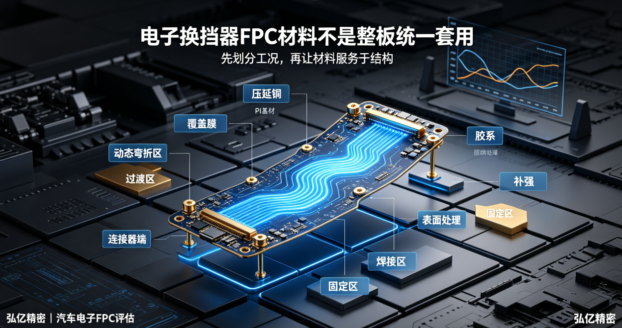
Different zones of an electronic shifter FPC experience distinct mechanical stresses—bending, soldering, and assembly forces—making a single-material solution across the entire board inappropriate. This article explains the selection logic for rolled annealed copper, polyimide (PI), coverlay, and stiffeners in dynamic, connector-end, and fixed zones.
Selecting materials for electronic shifter FPCs cannot be reduced to questions like 'What copper type?' or 'What thickness?' On a single FPC, the dynamic bending zone, connector end, soldering zone, and static fixed zone experience different mechanical loads—requiring zonal consideration of materials and stiffeners.
If an electronic shifter FPC manufacturer applies uniform thickness or uniform stiffening across the entire board, it may result in excessive rigidity in the dynamic zone, insufficient support at the connector end, or stiffener edges overlapping the actual bending path. A more robust approach is to first define the operational conditions, then select materials that serve the structural requirements.
I. First, segment into dynamic, transition, and fixed zones
The dynamic zone undergoes repeated bending during shifting actions; key parameters include bending radius, direction, cycle count, frequency, and trace fatigue resistance. The transition zone accommodates the shift between rigid and flexible behavior. Connector pads, solder lands, and screw-mount areas require dimensional stability and mechanical support.
Zone segmentation must reference 3D assembly models and extreme positional states—not just a 2D unfolded layout with an arc. Housing clips, harness pulling forces, and connector mating/unmating can all shift the true bending initiation point.
II. Why rolled annealed copper is frequently evaluated for dynamic bending zones
Rolled annealed copper generally offers superior elongation and bending adaptability for dynamic zones—but simply switching to rolled annealed copper does not guarantee reliable service life. Trace orientation, bending radius, copper distribution, total thickness, and coverlay design must be co-optimized.
The dynamic zone must also avoid via clustering, sharp corners, and abrupt trace width changes. Material selection addresses only part of the challenge; structural layout and routing determine whether the selected material performs as intended.
III. Polyimide (PI) substrate, coverlay, and adhesive system must be evaluated holistically
PI thickness and coverlay influence overall FPC thickness, flexibility, insulation protection, and localized stiffness. Overlapping coverlay windows, adhesive boundaries, and high-density trace regions may create new stress concentration points.
Automotive applications further demand evaluation of dimensional and insulation stability after thermal cycling, damp heat exposure, soldering, and long-term vibration—not just room-temperature static bend testing.
IV. Connector ends prioritize thickness and planarity
The connector end must match terminal geometry, mating direction, locking mechanism, and allowable thickness. Final end dimensions result from combined contributions of base substrate, copper foil, coverlay, stiffeners, and surface finish.
Stiffeners improve insertion/extraction support—but stiffener termination must not coincide with the primary dynamic bending initiation point. FPC manufacturers should verify stiffener length, thickness, and transition distance based on connector and housing tolerance stacks.
V. Fixed and soldering zones should not pursue excessive flexibility
Solder pads, connector solder tails, alignment holes, and screw-mount areas require sufficient rigidity to resist pulling or repeated bending during assembly. Local stiffening, pad windowing, and mounting datum features must be co-designed.
When a fixed zone abuts a dynamic zone, a gradual rigid-to-flex transition is essential to prevent stress concentration at trace roots. Specific transition distances must be validated against board thickness and motion trajectory.
VI. Material selection must be anchored in validation data
During prototyping, confirm that materials, stack-up, trace layout, and stiffeners match the planned mass-production configuration. Testing should cover dimensional accuracy, electrical performance, mating cycles, bending endurance, thermal cycling, vibration, and assembly per project requirements.
Any change in material, thickness, surface finish, or stiffener configuration requires re-evaluation of prior validation results. Identical material nomenclature alone does not justify reuse of legacy test data.
Materials documentation to submit to electronic shifter FPC manufacturers:
Gerber files, stack-up specifications, copper thickness, PI and coverlay requirements;
Marked zones: dynamic, connector end, soldering, and fixed;
3D assembly model, minimum bending radius, actuation cycles, and frequency;
Connector-end thickness, stiffener requirements, and surface finish specifications;
Temperature, vibration, soldering, and full-system validation standards;
Boundaries for material substitution and change approval.
Hongyi Precision provides engineering evaluation for FPC and FPCA solutions targeting automotive electronics—including electronic shifters, column-mounted shifters, and gear position sensors—with expertise in material stack-up, bending-zone design, stiffener integration, and connector-end optimization. We support prototyping, reliability validation, and volume production.
For connector-end structural details, refer to:Electronic Shifter FPC Connector-End Design; for supplier audit criteria, refer to:Electronic Shifter FPC Manufacturer Audit Guidelines.
Summary:Material selection for electronic shifter FPCs is not a one-size-fits-all exercise. Instead, dynamic zones prioritize bending adaptability, connector ends ensure assembly support, fixed zones manage mechanical load—and the entire combination must be validated under real-world operating conditions.