
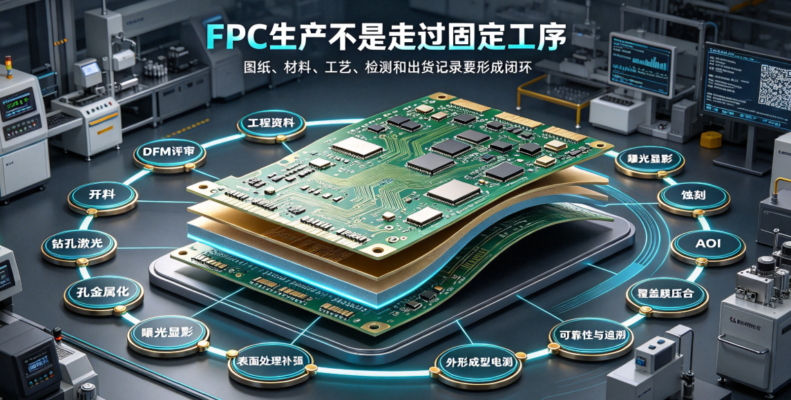
An FPC manufacturer’s production process is not a fixed checklist. This article outlines the 12 critical steps—from DFM, engineering data, materials, drilling, plating, circuit patterning, coverlay lamination, surface finishing, to electrical testing and traceability—and explains the quality control logic behind flexible PCB manufacturing.
First, the conclusion:FPC production is not a rigid sequence of fixed steps. Single-layer, double-layer, multilayer, rigid-flex, static-mount, and dynamic-bend products impose different requirements on drilling, copper plating, lamination, surface finishing, stiffener application, and reliability validation. A professional FPC manufacturer must first establish a controlled process flow based on drawings, materials, structure, and application conditions—then verify compliance at each critical step through first-article inspection, in-process checks, and shipment records.
Below, we outline the end-to-end manufacturing logic—from customer data entry to final shipment—for common single-layer, double-layer, and multilayer flexible PCBs. Specific projects may merge, split, or add steps; this article should not be treated as a universal, identical workflow for all products.
Step 1: Project Input and DFM Review
Before production begins, engineering personnel must confirm completeness of Gerber files, drill data, stack-up, materials, copper thickness, coverlay, stiffeners, surface finish, impedance, outline tolerances, and inspection specifications. For dynamic-bend products, bend zone location, direction, radius, stroke, frequency, and target lifetime must also be defined; automotive projects require additional inputs including temperature, vibration, traceability, and change-control requirements.
DFM’s role is not simply to reply 'feasible'—but to identify risks such as line manufacturability windows, annular rings, pads, coverlay openings, stiffener boundaries, and outline tolerances—and document customer sign-off. If input data remains unfrozen, even the most precise equipment cannot guarantee version accuracy.
Step 2: Engineering Documentation and Process Flow Development
After drawing approval, manufacturing instructions, panelization schemes, process compensation values, drill tapes, exposure data, inspection standards, and process cards must be established. Engineering compensation must account for etching, lamination, material expansion/contraction, and outline forming—but compensation values are not universal; they must be determined based on material system, board size, and historical process capability.
At this stage, key quality characteristics (KQCs) must also be defined—e.g., connector-end thickness, impedance, dynamic-bend zone traces, mounting hole location, and stiffener alignment. Each KQC must have a defined measurement method, frequency, and acceptance criterion.
Step 3: Base Material Receipt and Cutting Management
Common materials include polyimide (PI) substrates, copper foil, coverlay, adhesive film, stiffeners, and release liners. Incoming materials must be verified for supplier, grade, thickness, lot number, appearance, storage conditions, and shelf life. For applications sensitive to dimensional stability or bend performance, copper foil type and material combinations must be managed per approved specifications.
Cutting direction affects material utilization—and may impact performance of dynamic-bend products. After cutting, lot identifiers must be retained to preserve traceability throughout subsequent handling.
Step 4: Drilling, Laser Processing, and Pre-Drill Treatment
Double-layer or multilayer FPCs requiring interlayer connections typically undergo mechanical drilling or laser processing. Hole diameter, position, burr, and heat-affected zones influence subsequent metallization quality. Micro-vias, irregular geometries, and mixed-material stacks require process selection aligned with design intent and equipment capability.
Prior to metallization, hole-wall residues and surface condition must be addressed. Unstable cleaning, activation, or pre-treatment—even if the surface appears intact—can lead to insufficient hole-wall copper continuity or long-term reliability risks.
Step 5: Through-Hole Metallization and Copper Thickness Control
Double-layer and multilayer structures require interlayer conduction via electroless copper, electroplating, or project-specified processes. Control focuses not only on average copper thickness—but also on hole-wall coverage, uniformity, adhesion, and distribution across board areas.
Single-layer FPCs without plated-through holes may skip this step. Therefore, when evaluating an FPC manufacturer, do not merely ask 'Do you have a plating line?'—instead, confirm the specific route used for the target product, how it is measured, and how nonconforming lots are isolated.
Step 6: Dry Film Lamination, Exposure, and Development
Circuit patterns are transferred onto copper surfaces via dry-film lamination, UV exposure, and development. Cleanroom environment, film adhesion, exposure energy, registration accuracy, and development consistency directly affect fine-line resolution, spacing, and edge definition.
For fine-line projects, resolution capability and registration stability across board areas must be prioritized. Equipment nominal specifications alone cannot substitute actual first-article measurements and process capability data.
Step 7: Etching, Strip, and Line Dimension Verification
Etching defines final conductor geometry. Under-etching may cause residual copper or shorts; over-etching may reduce line width, pad neck dimensions, or local current-carrying capacity below design targets. Copper thickness, line density, and board location all influence etch results.
After stripping and cleaning, critical line widths, spacings, and pads must be measured per drawing or control plan. For high-density or high-reliability applications, cross-section analysis or other methods—not just visual inspection—are required to validate manufacturing outcomes.
Step 8: AOI and Mid-Process Electrical Risk Interception
AOI detects line-related defects such as opens, shorts, notches, residual copper, pinholes, and pattern deviations. Its value lies in identifying defects before coverlay lamination, lamination, or assembly—reducing downstream scrap.
However, AOI is not a universal inspection tool. Equipment parameters, reference data, and re-evaluation criteria must be controlled; issues involving hole walls, material interfaces, connector contacts, or dynamic lifetime require complementary inspection or validation methods.
Step 9: Coverlay Lamination and Pressing
Coverlay provides electrical insulation and mechanical protection. Lamination requires control of window positioning, air bubbles, wrinkles, adhesive squeeze-out, and foreign particles; pressing parameters must match material type, thickness, and board structure.
Coverlay and adhesive layer configurations near stiffener ends or bend initiation points alter local rigidity. In dynamic applications, verifying coverlay adhesion alone is insufficient—stress concentration at trace-stiffener-motion path interfaces must also be assessed.
Step 10: Surface Finishing, Stiffening, and Local Assembly
Pads and connection areas may receive ENIG, OSP, hard gold, or other approved surface finishes per project requirements. Selection must consider solderability, connector contact, storage, mating cycles, and reliability—not price alone.
PI, FR-4, or metal stiffeners control thickness and rigidity at connector ends, solder zones, and mounting areas. Post-lamination checks must cover placement accuracy, flatness, total thickness, and transition smoothness at boundaries. For FPCAs incorporating SMT or connectors, further control of solder paste, component placement, reflow profile, solder joint integrity, and functional testing is required.
Step 11: Outline Forming, Dimensional Inspection, and Final Electrical Test
Die-cutting, punching, laser cutting, or CNC machining define final outline geometry. Irregular branches, narrow necks, mounting holes, and connector ends are sensitive to dimensional reference; measurement methods must follow drawing specifications—avoid arbitrary stretching of flexible boards in free-state conditions to prevent erroneous conclusions.
Final electrical testing verifies opens, shorts, continuity, and insulation resistance—but passing electrical test does not guarantee compliance of thickness, outline, pads, stiffeners, or bend-life performance. FPC manufacturers must combine electrical, dimensional, visual, and project-specified functional checks to authorize release.
Step 12: Reliability Validation, Packaging, and Batch Traceability
Reliability tests must derive from real-world operating conditions—and may include bend cycling, thermal shock, humidity, vibration, soldering, peel strength, or assembly validation. Reports must specify sample version, sample size, equipment, fixtures, test conditions, monitoring methods, and failure criteria—not just state 'passed'.
Prior to shipment, part number, revision, quantity, lot number, inspection reports, labels, and packaging must be verified. Flexible boards must avoid transport-induced creasing, compression, moisture, contamination, and ESD risks. Alignment among material lot, production lot, critical process steps, and shipment lot enables rapid scope definition in case of anomalies.
Why Do Results Differ Across FPC Manufacturers for the Same Drawing?
Differences stem not only from equipment brands—but from engineering compensation, material lot control, parameter windows, inspection coverage, anomaly response, and operator experience. Two factories may both deliver samples—but that does not imply equivalent mass-production yield, batch consistency, or change-management capability.
During evaluation, request the manufacturer to demonstrate process flows comparable to your target product, first-article records, critical dimension data, AOI and electrical test methodologies, reliability test conditions, closed-loop anomaly records, and traceability fields. Generic marketing materials lacking specific part-number and revision alignment serve only for preliminary awareness.
How to Assess Whether an FPC Production Process Is Truly Controlled?
Drawings, materials, processes, and inspection documents share unified versions and formal approval status;
Key quality characteristics have clearly defined equipment, methods, frequencies, and acceptance criteria;
Each critical process step is traceable to material, lot, parameters, and inspection results;
Nonconforming units are physically isolated, root-caused, dispositioned, and re-validated;
Changes to materials, processes, equipment, or subcontractors follow notification and approval protocols;
The route used for sampling can be reasonably replicated in pilot and mass-production phases.
Hongyi Precision’s FPC Project Collaboration Approach
Dongguan Hongyi Precision Circuit Co., Ltd. supports automotive electronics, humanoid robotics, and consumer electronics projects—from drawing review and material/stack-up recommendations, through engineering prototypes, to FPCA and volume production. To understand the company’s overall positioning, refer toFPC Manufacturers and Flexible PCB Manufacturing Services; for manufacturing capabilities, seeFPC Manufacturing Processes and Production Capacity; for quality control, seeFPC Quality Inspection and Quality Management.
Before ramping to volume production, cross-check sample evidence, key quality characteristics, and approved boundaries usingFPC Sample Acceptance and Volume Production Release Methods. Specific process routes, lead times, and validation items are governed by customer drawings, product structure, order quantity, and mutually approved documents.
Summary:Assessing an FPC manufacturer’s professionalism requires more than counting listed process steps—it demands verification that the manufacturer can establish the correct route for each specific product, and that drawing revisions, material lots, process parameters, inspection data, and shipment records form a closed loop. Only a controlled production process enables stable replication of first-pass samples into consistent volume output.