
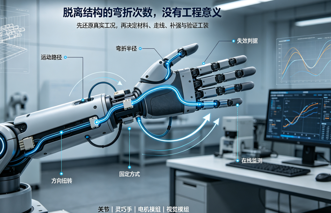
Robot FPCs are commonly used in joints, dexterous hands, vision modules, and motor connections—where repeated bending, twisting, and stretching collectively impact service life. This article outlines key conditions robot FPC manufacturers must confirm when evaluating dynamic reliability.
The reliability of robot FPCs cannot be summarized by a single metric such as 'how many bends it can withstand.' Motion profiles vary significantly across joints, fingers, wrists, vision modules, and motors—each imposing distinct bend radii, directions, speeds, torsional loads, and mechanical constraints on the FPC.
When evaluating dynamic life, robot FPC manufacturers must first reconstruct the actual motion path before selecting materials, stack-up configurations, trace routing, stiffener placement, and test fixtures. Bend counts derived without structural context do not directly correlate to in-system service life.
I. Differentiate static installation from dynamic interconnection
Static-installed FPCs primarily address assembly space, positioning, soldering integrity, and long-term environmental stability; dynamically connected FPCs must withstand copper fatigue, coverlay wear, stiffener-edge stress concentrations, and connector mechanical loading caused by repeated motion.
Customers must specify the target mounting location (e.g., joint or module), motion range, presence of torsion, daily actuation cycles, and expected service life. Only with this information can robot FPC manufacturers determine whether standard flexible interconnects suffice—or whether a dedicated dynamic-bend structure is required.
II. Motion path defines true stress distribution in the bend zone
Internal robot packaging is often highly constrained, causing the FPC to experience simultaneous bending, torsion, and lateral tension during operation. Distance between fixed points, exit direction, housing edge geometry, and connector support all influence neutral-axis location and localized stress.
Design reviews should include 3D models, motion trajectories, extreme pose definitions, and assembly sequence. Relying solely on flattened layouts risks overlooking pinch points, folding, or over-stretching at specific extreme positions.
III. Trace routing and material selection must align with motion direction
Dynamic bend zones should avoid sharp corners, dense via clusters, and abrupt changes in copper distribution. Trace orientation, copper type, total thickness, coverlay specification, and adhesive system must be jointly optimized based on minimum bend radius and target cycle count.
Stiffeners should be applied only where needed—for positioning, mating, or solder support—and transition smoothly to avoid encroaching on primary motion zones. Oversized, overly thick, or edge-proximate stiffeners may concentrate stress locally.
IV. Bend testing must specify at least eight parameters
Bend radius and direction;
Travel range or angular displacement;
Reciprocating frequency and target cycle count;
Fixed-point configuration, connector mounting, and fixture design;
Power state and real-time electrical monitoring;
Operating temperature and humidity;
Sample quantity and sampling method;
Resistance drift, intermittent opens, visual inspection criteria, and failure definition.
Without these boundary conditions, 'bend life' data reported by different robot FPC manufacturers lack direct comparability. Test reports must also document drawing revision, material lot numbers, and whether samples underwent full assembly.
V. Design focus differs for dexterous hand vs. joint FPCs
Dexterous hand FPCs often require high-density interconnects across fingers, palms, and tactile sensing zones—emphasizing compact form factor, branched geometry, pad layout, and sustained flexibility under repetitive motion. Joint FPCs prioritize rotational or oscillatory paths, fixed-point stability, torsional resistance, and connector retention.
FPCs inside motors or vision modules must additionally accommodate thermal sources, electromagnetic environments, tight packaging envelopes, and signal integrity requirements. A structure validated for one module cannot be directly replicated across all robot subsystems.
What to monitor from sample to mass production
Robot development cycles move quickly, and samples often undergo multiple revisions. Each revision must log changes to materials, stack-up, trace routing, stiffeners, connectors, and test fixtures—and identify which validations require re-execution.
During small-batch production, monitor dimensional consistency, electrical performance, bend-state repeatability, and assembly uniformity across lots. Hongyi Precision provides structural evaluation, rapid prototyping, dynamic reliability validation, and volume manufacturing support for FPC and FPCA solutions targeting humanoid robots, dexterous hands, joints, and motor modules.
Conclusion
When evaluating robot FPC manufacturers, avoid asking only 'How many bends can it survive?' Instead, assess whether the manufacturer can translate real-world motion conditions into actionable design constraints and test protocols. Only when bend radius, travel range, direction, fixation method, materials, trace routing, and in-line electrical monitoring are all clearly defined does bend-life data acquire engineering relevance.
Note:This article supports early-stage design and supplier communication for robot FPC projects. Specific lifetime targets, material selections, and acceptance criteria must be finalized per full-system operating conditions, customer drawings, and joint validation results.