
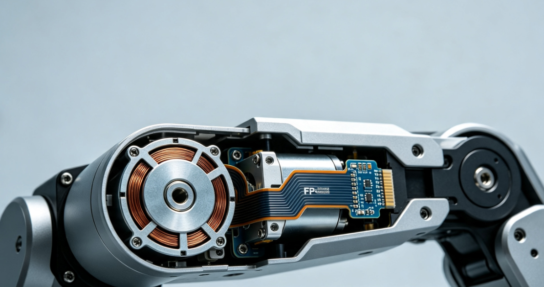
FPC for coreless motors must balance precision circuitry, non-standard outlines, solder interface integrity, and assembly reliability within highly constrained spaces. This article outlines key design considerations—including coil patterns, material stack-up, outline definition and positioning, pad interconnects, and prototyping validation—based on publicly available parameters of existing products.
Coreless motors are commonly used in humanoid robot dexterous hands, small-joint actuators, and precision motion modules. Internal space within such modules is extremely limited; the FPC must not only provide electrical connectivity but also conform to circular or irregular geometries, accommodate specific solder locations, and support mechanical fixation.FPC Solution for Humanoid RobotsWhen evaluating an FPC solution for humanoid robots, verifying simple continuity is insufficient. Trace width/spacing, copper thickness, outline tolerance, pad architecture, and actual assembly constraints must all be integrated into a unified set of design inputs.
Why does FPC for coreless motors require dedicated evaluation?
Coreless motors and their associated subassemblies typically allocate minimal space for routing. Circumferential layout, lead-out positions, and connector placement directly influence FPC outline geometry. Proximity to high-speed moving components introduces risks: inadequate fixation may cause misalignment, abrasion, or solder joint stress; excessive clamping may convert assembly tolerances into localized mechanical stress. Therefore, FPC design must simultaneously meet electrical, structural, and assembly requirements—standard ribbon cables cannot be simply downscaled for this application.
First, define trace pattern and material stack-up
Trace width and spacing must allow for stable, repeatable manufacturing
Hongyi Precision’s existingcoreless motor FPCpublicly disclosed parameters include 1–2 layer constructions, minimum trace/space of 50/50 µm, and copper thickness options of 9 µm, 12 µm, and 18 µm. These figures reflect current production capability—not universal design rules. Actual trace width, copper thickness, and layer count must be jointly determined based on current rating, allowable temperature rise, trace length, spatial constraints, and target volume, while reserving appropriate margins for etching and registration accuracy.
PI substrate thickness must be coordinated with outline geometry and assembly method
Available PI substrates include 12.5 µm and 25 µm thicknesses. The combined stack-up—including PI base film, copper foil, adhesive layer, and coverlay—determines final thickness and flexibility. Thinner materials do not inherently improve assembly reliability; stress concentration may still occur at transitions near connectors, mounting edges, or contour changes if proper relief features are omitted. During project review, identify zones requiring flexibility versus those needing rigid support, aligned with the actual installation path.
Circular and non-standard outlines must be designed around assembly datums
Coreless motor FPC outlines can be formed via precision die-cutting or laser cutting. Hongyi Precision’s publicly cited outline tolerance example is ±0.05 mm; however, project-specific tolerances must be confirmed based on pattern dimensions, material stack-up, positioning method, and volume capability. Design inputs must explicitly specify motor cavity dimensions, mounting datums, lead-out direction, keep-out zones, and connector location—to prevent FPC edge interference with housing or moving parts.
Positioning holes, notches, and corners should not be placed solely per 2D layout. Fixture design, soldering orientation, and operator access all affect positioning effectiveness. Avoid abrupt geometric or copper density transitions at arc-to-narrow-neck junctions, and ensure sufficient operational clearance for subsequent placement, soldering, and inspection.
Pad design and surface finish determine connection stability
Existing coreless motor FPCs from Hongyi Precision support ENIG or electroplated gold surface finishes, selected to match specific soldering and mating requirements. Surface finish selection must consider solder process, contact type, storage conditions, and reliability targets—not aesthetics alone. Pad dimensions, coverlay window size, pad-to-trace transition geometry, and localized stiffener placement must be jointly reviewed with customer terminals and soldering parameters.
If the connector end experiences assembly tension or repeated vibration, verify anchoring location and load transfer path to avoid concentrating stress at the pad root. Stiffeners are not always beneficial—their edge position, thickness, and bonding area must avoid regions requiring dynamic bending or tolerance accommodation.
Validate signal integrity and motion interaction within full robot integration
Coreless motors may share confined finger or palm space withdexterous hand sensor FPCor integrate withjoint sensor FPCto form drive-and-feedback loops. Designers must distinguish between motor power connections, sensor signals, and motion paths—confirming spatial relationships, mounting points, and assembly sequence among traces. For continuously flexing interconnect zones, refer separately toFPC Bend Design Guidelines for Humanoid Robot Jointsto assess motion trajectory and stress boundaries.
100% electrical testing cannot replace physical assembly validation
Hongyi Precision performs 100% electrical testing on existing coreless motor FPCs to screen for opens, shorts, and continuity anomalies. However, electrical testing does not substitute for outline verification, solder joint assessment, or full-system operational validation. During sampling, inspect critical dimensions, positioning consistency, solder joint quality, and post-assembly clearances. Vibration, thermal cycling, or lifetime testing may be required per project specifications.
Validation fixtures should replicate actual mounting points, lead-out directions, and installation envelope as closely as possible. Document appearance, dimensions, resistance, and connection status before and after testing to differentiate issues arising from FPC fabrication, soldering/assembly, or mechanical interference—and establish objective criteria for future volume control.
What documentation is recommended prior to prototyping?
Motor cavity dimensions, mounting datums, lead-out direction, and keep-out zone specifications.
Schematic, operating current/voltage, allowable temperature rise, and interconnect definitions.
Specified or constrained layer count, copper thickness, PI thickness, and surface finish.
Pad geometry, terminal type, soldering method, fixation method, and assembly sequence.
Critical outline tolerances, positioning methodology, and sample acceptance criteria.
Applicable full-system validation conditions—including vibration, temperature, and lifetime requirements.
The core objective of coreless motor FPC design is to align trace capability with motor geometry, solder interface requirements, and humanoid robot assembly constraints. Providing complete spatial, electrical, and validation data early significantly increases the likelihood of identifying outline, positioning, and interconnect risks before prototyping—reducing iterative redesign cycles. For manufacturability review against engineering drawings, pleasesubmit coreless motor FPC project documentation.