
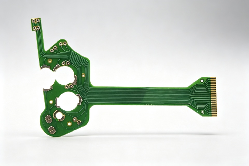
FPCs for humanoid robot joints must route sensing, driving, and control signals within tight spatial constraints while enduring repeated motion, continuous vibration, and assembly-induced stress. This article outlines pre-prototyping design checkpoints—including flexible/rigid zone partitioning, bend path planning, vibration-resistant positioning, surface finish selection, and validation methodology.
Humanoid robot joints typically house sensors, motors, control boards, and connectors in highly constrained internal spaces. Flexible Printed Circuits (FPCs) enable thin, conformal routing along joint contours—but face more than simple bending: articulation induces repeated flexing and torsion; motor operation generates vibration; and assembly misalignment may impose additional tensile strain. Achieving stable interconnection requires integrated evaluation of trace layout, stack-up, mounting method, and real-world motion path.
Common FPC types used in robot joints
Joint sensor FPCs
Angle, position, and status sensors require flexible interconnection to control electronics. Such FPCs emphasize compact routing, robust pads, and reliable signal integrity—with surface finish selected per operational environment.
Rigid-flex FPCs
Rigid-flex constructions integrate component-mounting zones, connector areas, and dynamic flex regions. Rigid sections support component placement and mechanical anchoring; flexible sections bridge moving joints or accommodate articulation. Transition design between rigid and flex zones directly impacts long-term assembly stability and reliability.
Motor and actuator interconnect FPCs
Coreless motors and miniature actuators feature compact geometries with stringent requirements on form factor, coil pattern, solder interface, and mounting. Their FPC design differs from sensor-focused layouts and must be evaluated separately—considering motor dimensions, interface type, current rating, and rotational speed.
What requires special attention in dynamic bend zones?
1. Confirm the actual motion trajectory first
Design must not rely solely on 2D schematics to locate bend zones. Integrate joint rotation direction, travel range, mounting points, and housing envelope to determine how the FPC bends, rolls, or twists within the assembled system. Misalignment between theoretical bend zones and actual motion paths risks stress concentration at housing edges or stiffener termini.
2. Avoid abrupt stiffness changes in flex zones
Dynamic regions should minimize pads, vias, stiffener edges, and sudden copper distribution shifts. Traces should follow smooth transitions, with orientation optimized for primary bend direction. Coverlay, adhesive layer, copper thickness, and base film collectively define total thickness and neutral axis position—lifetime cannot be improved by changing only one material.
3. Distribute stress across rigid-flex transitions
The junction between rigid and flex zones is prone to pull-out under cyclic loading. Positioning holes, mating limits, and mechanical fixation reduce long-term vibrational shift—but fixed edges must not reside within active motion zones. Assembly design should confine FPC movement to designated regions—not random bending at connector roots.
Why distinguish pad zones from general trace areas?
Connectors, solder pads, and exposed contact zones in robot joints demand consideration of solderability, mating cycles, oxidation resistance, and environmental exposure. Covered traces prioritize flexibility, cost, and manufacturing consistency. Selecting appropriate finishes—e.g., ENIG or tin plating—balances critical interconnect reliability against cost. Final process choice must align with solder method, environmental class, and qualification standards—not nominal naming alone.
Signal, power, and mechanical design must be co-optimized
Joint FPCs often carry sensor signals, motor power, and control lines simultaneously. Design reviews must specify current capacity, trace width/spacing, impedance targets, grounding strategy, and EMI mitigation—and cross-check manufacturability constraints including minimum outline, pad pitch, and connector placement. For high-density sensor nodes, ensure signal timing consistency and comprehensive test coverage.
Recommended documentation prior to prototyping
Joint assembly drawings, available routing space, and FPC mounting locations.
Motion direction, angular range or stroke, plus bending and torsional behavior.
Electrical requirements for sensing, power, and control signals.
Connector specifications, soldering method, stiffener requirements, and positioning features.
Operating temperature, vibration profile, humidity, or salt fog exposure conditions.
Target validation items, actuation frequency, and failure criteria.
Reliability validation must mirror full-joint assembly conditions
Basic electrical testing confirms opens, shorts, and connectivity—but cannot substitute for dynamic validation. For moving joints, use jigs replicating real-world motion paths during testing, while monitoring key circuits in real time. Additional tests—vibration, thermal cycling, damp heat, or salt fog—may apply per project requirements. Compare visual inspection, dimensional checks, and electrical performance pre- and post-test; perform focused analysis on bend zones, rigid-flex transitions, and pad roots to identify risk locations.
There is no universal FPC solution for humanoid robot joints independent of full-system integration. The earlier the motion trajectory, mounting envelope, and environmental specs are provided, the sooner bend, fixation, and interconnect risks can be identified pre-prototyping—reducing iterative redesign and establishing verifiable standards for mass-production assembly consistency.