
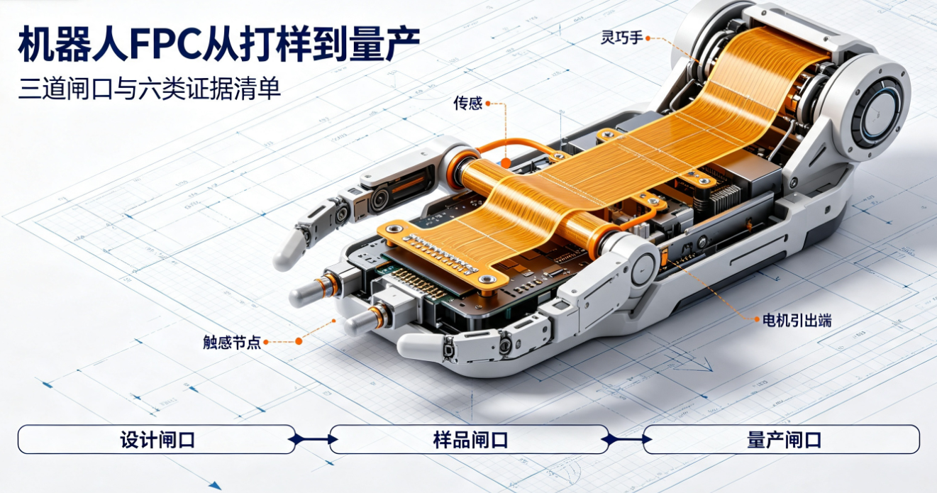
Evaluating an FPC supplier for robotics cannot rely solely on equipment lists, quotations, or whether samples pass continuity testing. This article outlines the required evidence across six areas—design input, DFM, material stack-up, sample replication, reliability validation, batch traceability, and change management—using three application categories: joint sensing, dexterous hand interconnects, and coreless motor interfaces.
Direct answer:Evaluating an FPC supplier for robotics requires more than comparing equipment count, minimum line width/spacing, quotation, or lead time. A more effective approach is to verify whether the supplier can consistently deliver six categories of traceable evidence—application and motion boundaries, DFM and stack-up rationale, sample manufacturing records, real-condition validation, failure closure, and batch traceability and change control—all anchored to the same set of project inputs. Only when these evidences align with the same drawing revision, same sample batch, and same acceptance criteria does the supplier demonstrate readiness to move from ‘capable of prototyping’ to ‘qualified for mass production review.’
This article is compiled by Dongguan Hongyi Precision Circuit Co., Ltd. based on publicly available product documentation and common project review logic. Hongyi Precision publicly offersrobotics FPC manufacturers and humanoid robot flexible circuit board solutionscovering joint sensing, dexterous hand tactile interconnects, coreless motors, and related precision modules. Product parameters cited herein serve only to illustrate evaluation methodology and do not imply uniform specifications across all robotics projects; final solutions must be confirmed per customer drawings, full-system operating conditions, and mutually approved documents.
Step one is not reviewing specs—it’s defining application boundaries
FPCs inside robots do not operate under identical conditions. Joints, dexterous hands, vision modules, and motor interconnects impose distinct requirements on space, current-carrying capacity, signal integrity, mounting methods, and flex-life endurance. If RFQ materials simply state ‘FPC for robotics,’ suppliers can only quote based on generic experience—making it difficult to substantiate whether materials, stiffeners, routing strategies, and validation conditions truly match the host system.
Joint sensing: Confirm motion trajectory and mounting points first
Humanoid robot joint sensor FPCsmay simultaneously endure assembly bending, sustained vibration, and repetitive joint articulation. Project inputs must explicitly identify which zones bend once during assembly versus those subjected to long-term dynamic motion—and specify mounting points, travel range, bend radius, frequency, target cycle count, connector loading, and maintenance method. Without clear demarcation between dynamic and static zones, subsequent material selection and lifetime assumptions lack technical grounding.
Dexterous hand: Assess high-density signals alongside tight spatial constraints
Dexterous hand sensor FPCsmust route multiple tactile nodes within limited finger or palm space. Beyond netlist relationships, confirm signal type (e.g., analog, digital), line width/spacing, shielding or grounding needs, branch locations, mounting method, and assembly sequence. Localized increases in routing density may introduce risks at narrow necks, coverlay openings, or stiffener edges—electrical continuity testing alone cannot substitute for full assembly review.
Coreless motor: Prioritize outline, soldering, and motion interference verification
Coreless motor FPCsoften feature circular or custom outlines and require precise pad connections and lead-outs within compact cavities. Review must verify motor internal cavity dimensions, mounting datums, lead-out direction, solder pad location, outline tolerance, and clearance against moving components. Specific inspection methods for trace geometry, materials, pads, and assembly are detailed in theCoreless Motor FPC Design Guide.
What six categories of evidence should a robotics FPC supplier provide?
1. Design Input and DFM Evidence
Effective DFM goes beyond stating ‘manufacturable.’ Suppliers must annotate Gerber files, schematics, mechanical drawings, and assembly instructions—including stack-up, bend zones, trace transitions, stiffener coverage, coverlay openings, pad connections, and manufacturability windows—and list unresolved risks. Review records must be traceable to drawing revision, responsible personnel, and closure conclusions. Hongyi Precision’s publicly availableFPC Manufacturing and Engineering Capabilitiesserve as a reference for process scope—but equipment or capability webpages alone cannot replace project-specific DFM documentation.
2. Material Stack-Up and Selection Rationale
Layer count, copper thickness, PI thickness, copper foil type, adhesive system, and coverlay collectively determine current capacity, thickness, flexibility, and process window. Suppliers must justify why a specific stack-up was selected—and how that choice addresses current rating, thermal rise, static/dynamic flexing, solderability, and environmental requirements. Highlighting terms like ‘thinner,’ ‘rolled annealed copper,’ or ‘automotive-grade materials’ alone does not prove suitability; material names must be evaluated jointly with structural design and validation conditions.
3. Sample Manufacturing and Replication Evidence
Passing first-sample inspection only confirms compliance under current test conditions. Prior to mass production review, verify key material lot numbers, trace formation, coverlay registration, stiffener lamination, surface finish, critical dimensions, and electrical results—and confirm alignment between sample process and planned production process. If samples depend on ad-hoc rework, manual sorting, or undocumented operator adjustments, single-batch results cannot represent stable mass production capability.
4. Reliability Evidence Aligned with Real Operating Conditions
Flex-cycle counts are only comparable when accompanied by tooling, bend radius, travel distance, frequency, mounting method, in-line monitoring, and failure criteria. Temperature, vibration, humidity-heat, or media exposure tests must specify sample size, duration, and pass/fail standards. For joint applications, refer to theRobot Joint FPC Dynamic Flex Design Guidelinesto assess whether test fixtures replicate actual mounting points and motion constraints.
5. Failure Analysis and Corrective Closure
When open circuits, resistance drift, pad root cracking, coverlay delamination, or mechanical interference occur, suppliers must distinguish root causes across material, trace, structure, process, and assembly—and retain analysis, corrective action, and revalidation records. Simply swapping materials or increasing inspection frequency rarely eliminates root cause. Effective closure requires explicit linkage to drawing revision, sample lot, failure location, corrective action, and retest results.
6. Batch Traceability and Change Control
During mass production, traceability must cover critical materials, production lots, process parameters, dimensional data, and electrical results—and agreed protocols must define notification, approval, and revalidation requirements for changes to materials, stack-up, equipment, processes, or subcontractors. Refer toQuality and Reliability Managementfor publicly disclosed quality system information—but project-specific traceability fields, retention periods, sampling plans, and change approval workflows must be documented in mutual agreements.
How should publicly listed product parameters be used for supplier comparison?
Publicly listed parameters support early-stage screening and technical dialogue—not direct, condition-agnostic specification matching. Using existing Hongyi Precision public examples:
Dexterous hand sensor FPC examples include 1–4 layers, 50/50 µm minimum line width/spacing, 9 µm or 12 µm rolled annealed copper, 100% electrical testing, and neutral-axis and dynamic-flex zone design.
Coreless motor FPC examples include 1–2 layers, 50/50 µm minimum line width/spacing, precision die-cutting or laser cutting, ±0.05 mm outline tolerance example, and 100% electrical testing.
Joint sensor FPC examples include 1–2 layers, 12.5 µm or 25 µm PI, optional ENIG or tin plating surface finish, -40°C to +105°C operating temperature example, and 100% electrical testing.
These parameters indicate established manufacturing approaches for respective products—but do not guarantee identical outcomes for new projects. Buyers must still submit their own trace layouts, dimensions, current ratings, environmental profiles, motion profiles, and acceptance criteria for supplier re-evaluation.
Before comparing quotations, standardize these eight inputs
Controlled-revision Gerber files, schematics, BOM, and electrical net definitions.
2D dimensions, 3D assembly models, mounting points, connectors, keep-out zones, and assembly sequence.
Bend radius, travel distance, frequency, target cycles, and allowable failure criteria for static bends or dynamic motion.
Operating and storage temperature, vibration, humidity-heat, salt fog, or other media exposure conditions.
Layer count, copper thickness, PI thickness, copper foil type, surface finish, and stiffener constraints.
Critical dimensions, electrical performance, visual appearance, impedance, or other acceptance items and pass/fail criteria.
Sample quantity, planned production volume, delivery milestones, and traceability requirements.
Notification, approval, and revalidation rules for material or process changes.
Only with consistent RFQ inputs do price, lead time, and technical proposals become meaningfully comparable. Otherwise, lower quotes may reflect differences in materials, testing scope, traceability depth, or acceptance criteria—not efficiency gains within identical solutions.
From prototyping to mass production: Three recommended review gates
Design Gate:Confirm complete inputs, closed DFM risks, controlled stack-up and drawing revisions, and output a review-ready design and manufacturing plan.
Sample Gate:Verify traceable sample materials, processes, dimensions, electrical performance, and assembly results—and complete validation aligned with real operating conditions.
Production Gate:Confirm sample process replicability on planned production lines, and that traceability, sampling, exception handling, and change control are formally documented and approved.
If any gate remains unclosed, proceeding directly to mass production based solely on quotation, lead time, or single-sample results is not advisable.
Common Questions
Does more equipment mean stronger robotics FPC capability?
Not necessarily. Equipment lists only indicate potential processing capabilities—they cannot substitute for project-specific DFM, sample records, reliability reports, or batch traceability. Ultimately, evidence must align with the same drawing revision and same acceptance criteria.
Does 100% electrical testing prove reliability?
No. Electrical testing screens for opens, shorts, and continuity anomalies under current conditions—it does not guarantee long-term reliability after flexing, thermal cycling, vibration, or mechanical stress during assembly and operation.
Are thinner robotics FPCs always better?
No. Reducing thickness may lower local bending stiffness but must still satisfy current-carrying capacity, trace manufacturability, pad connection integrity, stiffener integration, assembly compatibility, and mechanical strength. Final thickness must be determined jointly by stack-up and real-world operating conditions.
Can ‘one million flex cycles’ be directly compared across suppliers?
Cycle count alone is not comparable. Differences in test radius, travel distance, frequency, mounting method, sample size, in-line monitoring, and failure criteria render raw cycle numbers meaningless. First harmonize test conditions—then compare results.
What is the minimum required before prototyping?
At minimum: controlled drawings, electrical definitions, 3D assembly models or critical dimensions, motion/environmental boundaries, material constraints, acceptance items, and target sample quantity. The more complete the input, the earlier routing, outline, and validation risks can be identified.
Selecting a robotics FPC supplier hinges on verifying every claimed capability with project-specific evidence—not stacking specs and marketing language. For manufacturability assessment aligned with joint, dexterous hand, or motor module drawings, pleasesubmit your robotics FPC project documentationand specify assembly, motion, and acceptance boundaries during the quotation phase.